In this issue:
Implant Spacing and Selection in the Posterior
Author

Note: The Hahn Tapered Implant System is now known as the Glidewell HT Implant System
Implant selection and positioning can be confidently addressed with thorough, prosthetically driven treatment planning. The appropriate size and spacing of dental implants in the posterior is determined by carefully assessing the anatomy of the ridge, the restorative space available, and the long-term needs of the patient.
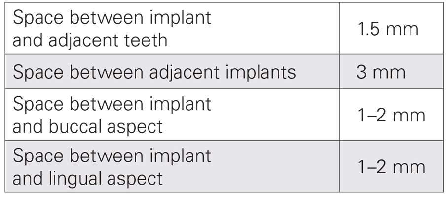
The edentulous span must be evaluated to identify the appropriate implant size for each site. First, the mesial-distal distance between the teeth adjacent to the edentulous space is measured. Then, the implant sizes are determined, allowing for 1.5 mm of space between the shoulder of each implant and the neighboring tooth, and 3 mm between adjacent implants. Buccolingually, allow for 1–2 mm of bone on each side of the implant.
RESIDUAL RIDGE IN THE POSTERIOR: POSITIONING THE IMPLANTS
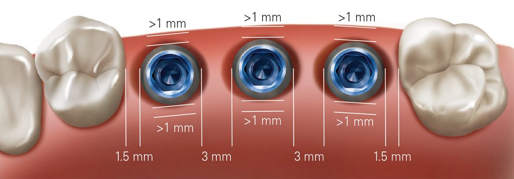
When treating a residual ridge in the posterior, position the implants a minimum of 1.5 mm from neighboring teeth and 3 mm from adjacent implants.
CASE REPORT
The following case shows how to navigate the implant spacing and selection considerations for restoration of an edentulous span in the posterior. By properly evaluating the residual ridge and surrounding anatomy, and positioning the implants to support the ideal prosthetic outcome, dental function is restored for the patient predictably and efficiently despite the presence of a large buccal defect at the time of implant placement.
By properly evaluating the residual ridge and surrounding anatomy, and positioning the implants to support the ideal prosthetic outcome, dental function is restored for the patient predictably and efficiently.
With an edentulous span measuring approximately 26 mm long, the diameter of the three implants was calculated as follows:
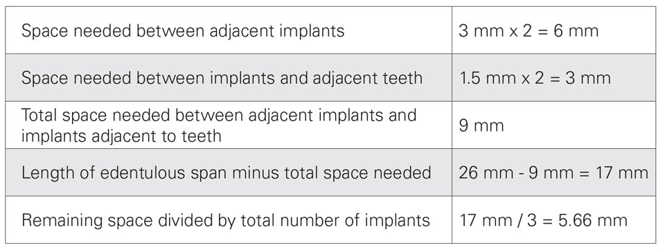
Note: Although the above calculation indicated sufficient space for three 5.0 mm implants, the significant buccal defect called for a more conservative approach in which 4.3 mm implants were selected for the surgical procedure to allow for additional space between the implant in the area of tooth #29 and the defect. Further, the 4.3-mm-diameter size allowed for the recommended minimum of 1 mm of bone on the buccal and lingual aspects of the implants.
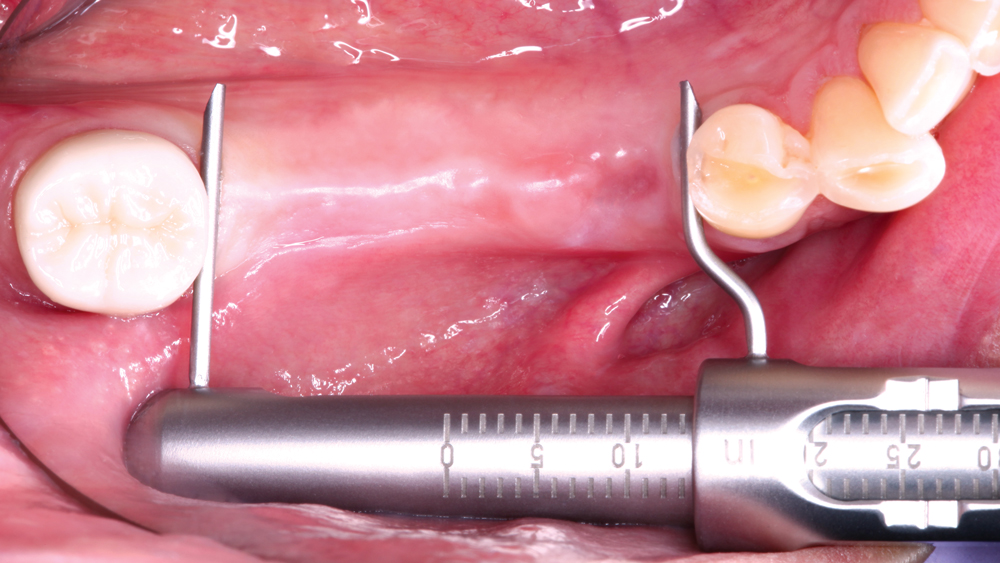
Figure 1: The patient sought implant treatment for an edentulous space spanning teeth #29–31, which were extracted three years prior due to severe dental caries. Unhappy with the function of a removable partial denture, the patient desired implant treatment to improve his chewing capabilities. The mesial-distal length of the residual ridge, which helps determine the appropriate size of implants to place, was measured and found to be 26 mm.
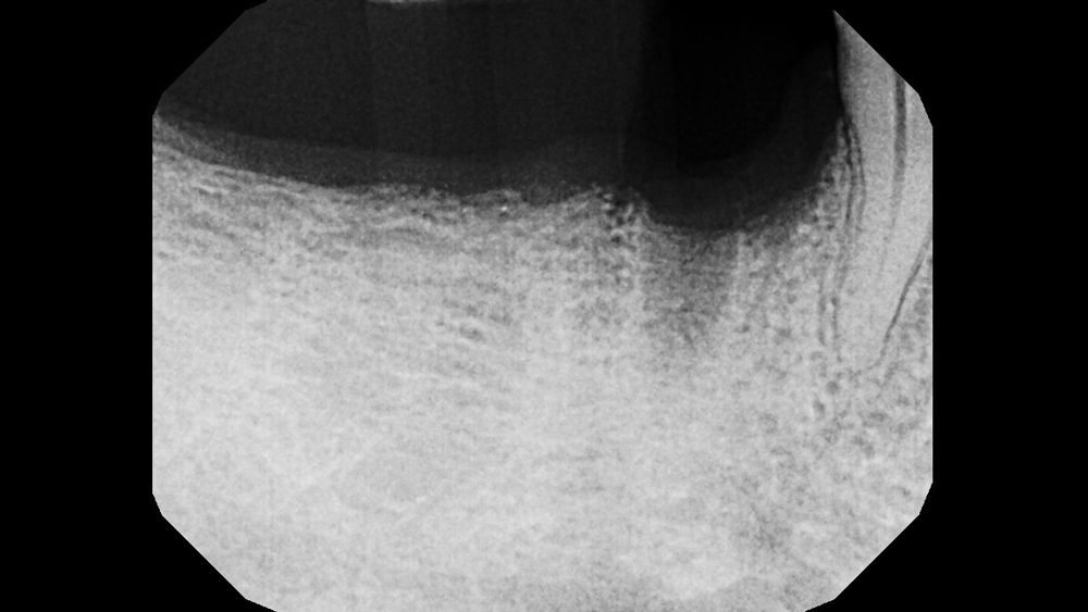
Figure 2: Initial radiography illustrated adequate vertical bone height along the posterior residual ridge, as well as a defect in the area of tooth #29. The patient preferred to have all three implants placed at the initial surgical appointment in order to minimize surgical incisions. However, it could not be determined whether an implant could be placed in the area of tooth #29 at the time of grafting without first reflecting a flap and performing a direct evaluation.
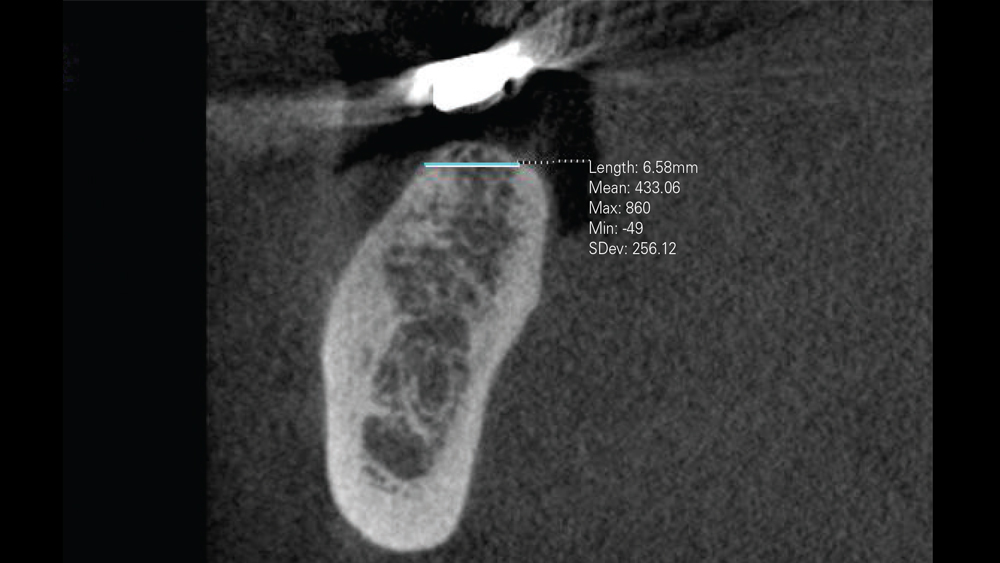
Figure 3: CBCT analysis indicated approximately 6.6 mm of residual ridge width, confirming sufficient space for the placement of three 4.3 mm implants. The CBCT scan also helped pinpoint the location of the inferior alveolar nerve and the mental foramen for surgical treatment planning purposes. The location of the patient’s mental foramen in the apical area of the patient’s first and second molar affected both the flap design and the location of the osteotomy for the implant in the area of tooth #29.
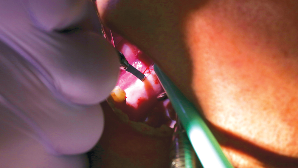 Figure 4a
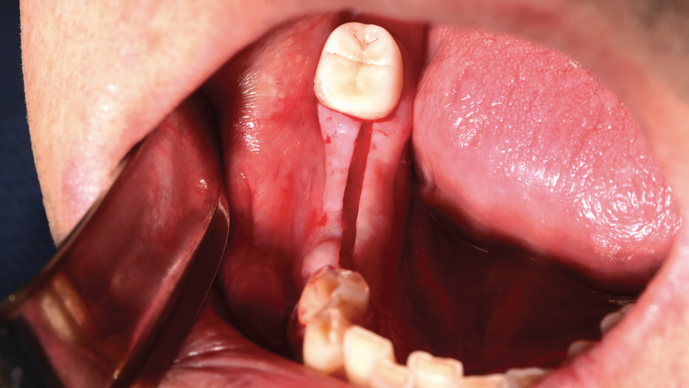 Figure 4b
Figures 4a, 4b: A full-thickness incision was made so a flap could be reflected to expose the ridge for evaluation and treatment. The incision extended around the tooth to the mesial of the edentulous span so the ridge could be exposed without making a vertical releasing incision, which helped avoid endangering the mental foramen.
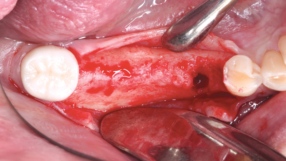
Figure 5: Occlusal view of the residual ridge following flap reflection. Direct evaluation of the residual ridge and the buccal defect in the area of tooth #29 confirmed that enough bone was available to place all three implants, graft the site, and attain sufficient primary stability. The buccal defect was thoroughly cleaned with a curette to remove any granulation tissue.
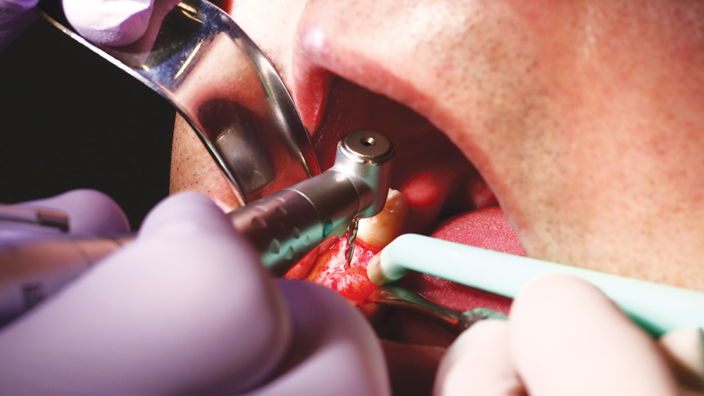
Figure 6: The osteotomies were created following the straightforward surgical protocol of the Hahn™ Tapered Implant System (Glidewell Direct; Irvine, Calif.), which was selected for the implant’s ability to achieve high primary stability. Additionally, the implant’s tapered body design provided an additional margin of distance from the defect and mental foramen.
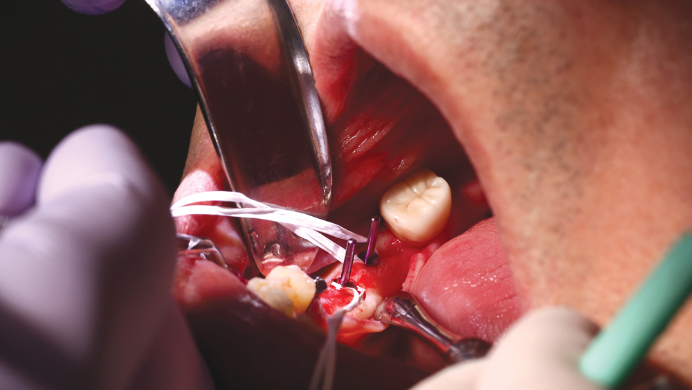 Figure 7a
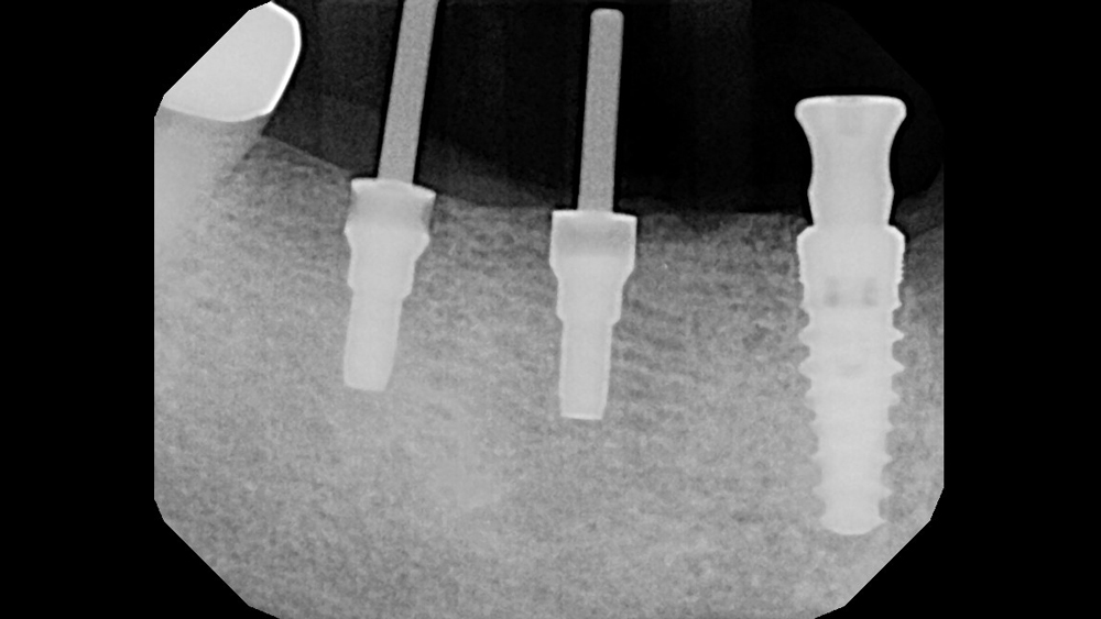 Figure 7b
Figures 7a, 7b: Parallel pins were used to confirm proper positioning of the implant osteotomies as surgery progressed. Note that the implant in the area of tooth #29 was positioned more distally to avoid the buccal defect.
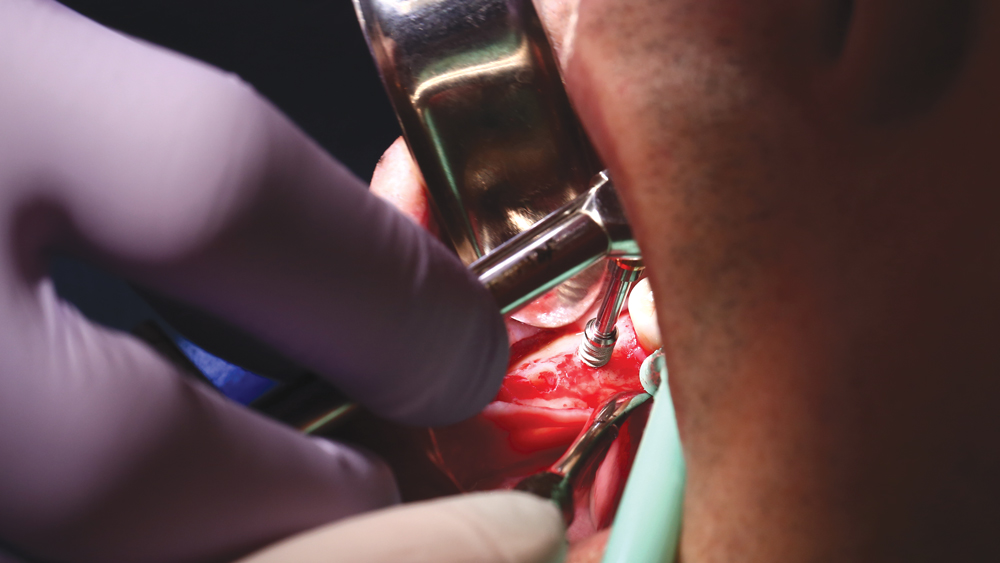
Figure 8: The Hahn Tapered Implants were tightened into final position using a torque wrench. The patient’s favorable ridge width allowed for positioning of the three implants at close to a 90-degree angle within the central fossa of the planned restoration. This positioning facilitated the desired method of screw-retention, which offers many advantages, particularly in the posterior.
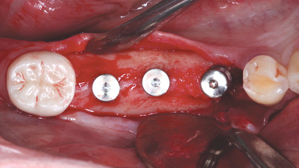
Figure 9: Occlusal view of implants in final position. The primary stability of the implants was excellent, so healing abutments were attached to contour the soft tissue during the period of osseointegration.
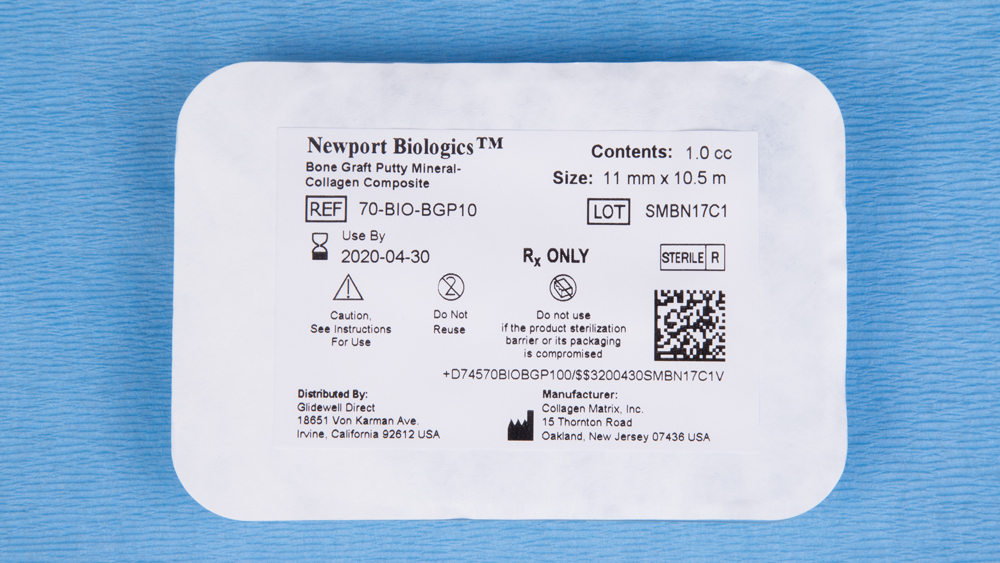 Figure 10a
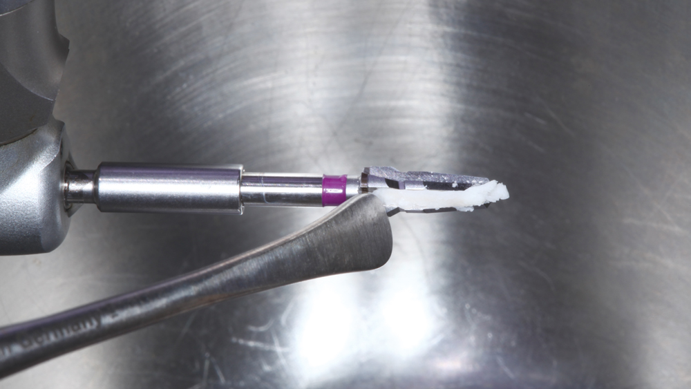 Figure 10b
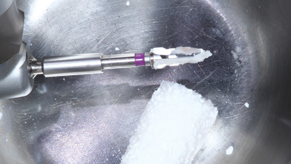 Figure 10c
Figures 10a–10c: Newport Biologics™ Bone Graft Putty Mineral-Collagen Composite (Glidewell Direct), which disperses calcium phosphate-based mineral particles within collagen fibers to form a three-dimensional matrix for bone regeneration, was selected to graft the defect because of its handling properties and moldability. The patient’s native bone was removed from the surgical drills following osteotomy creation and blended with the bone graft putty in a dappen dish.
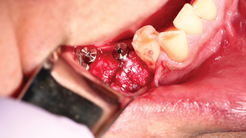
Figure 11: The prepared Newport Biologics bone graft putty was flattened, molded and positioned in the area of the defect to reconstitute the natural shape of the mandibular ridge.
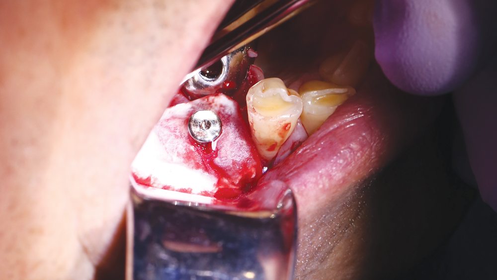 Figure 12a
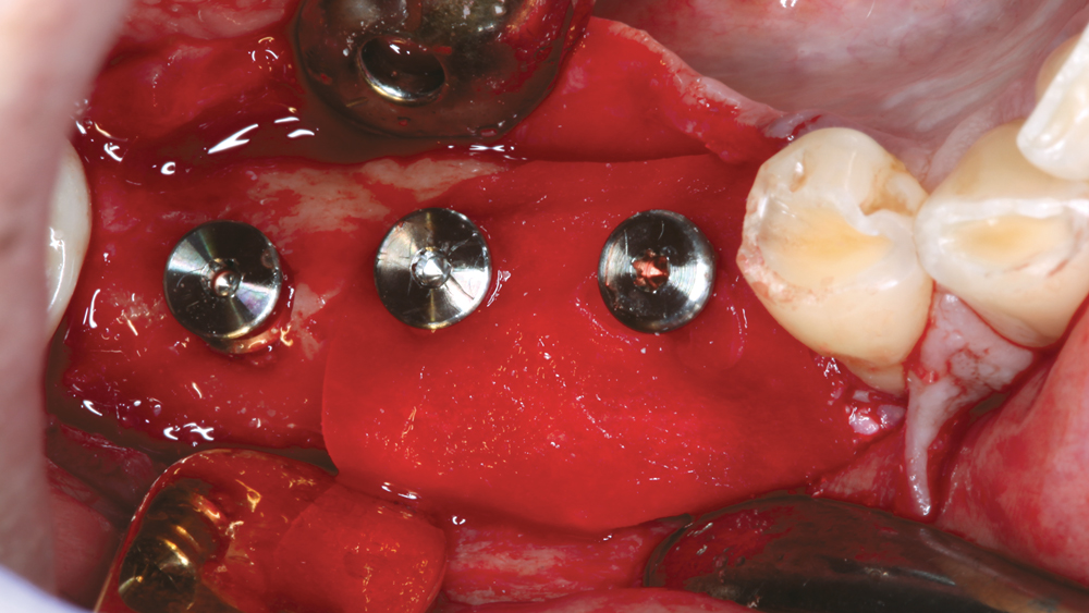 Figure 12b
Figures 12a, 12b: A Newport Biologics Resorbable Collagen Membrane 3-4, which is strong yet highly drapable, was used to secure the bone grafting material in place. Holes were punched in the membrane so it could be positioned over the healing abutments and draped over the ridge to cover the defect, serving to secure the grafting material during bone regeneration.
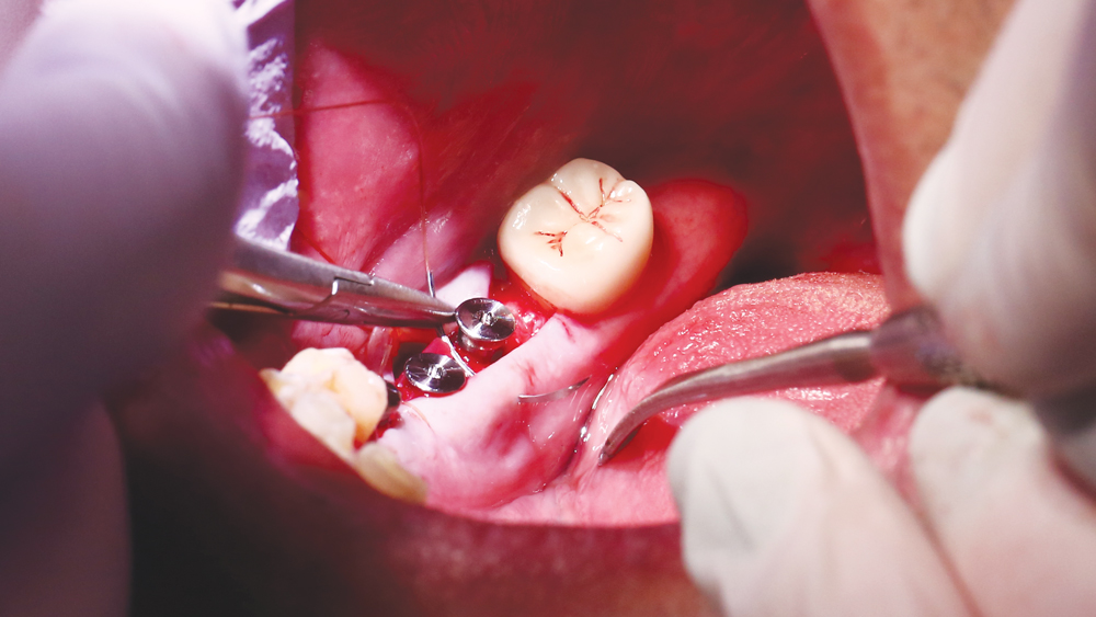
Figure 13: A PTFE suture was used with a horizontal mattress technique to close the site near the defect, and the remaining area of treatment was closed using chromic interrupted sutures.
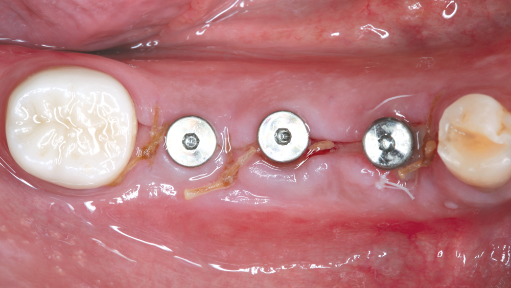
Figure 14: One-week post-op occlusal view illustrates ideal primary closure of the implant and bone grafting sites.
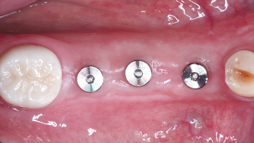 Figure 15a
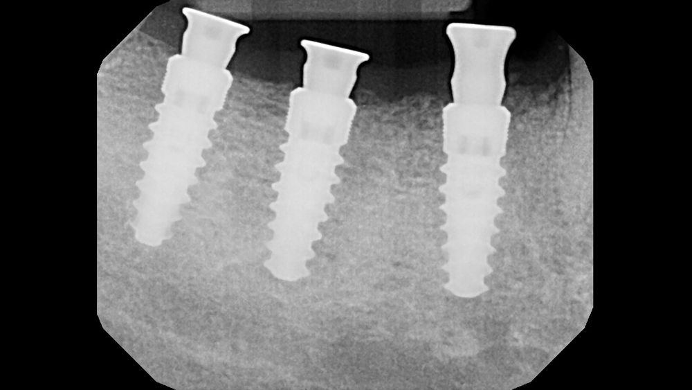 Figure 15b
Figures 15a, 15b: Four months after implant placement, the patient returned for evaluation and impression-taking. Excellent bone regeneration was observed in the area of the buccal defect.
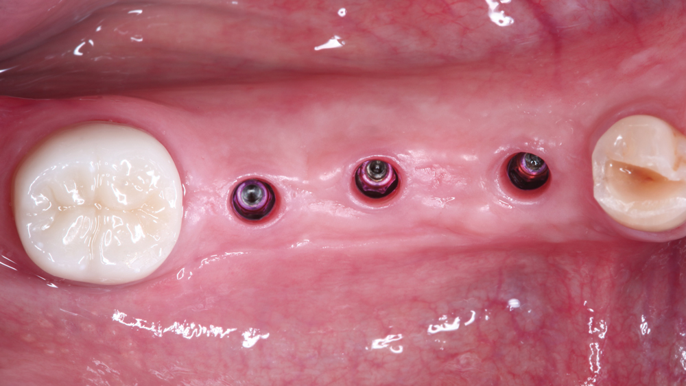
Figure 16: The healing abutments were removed, exhibiting healthy soft-tissue volume and thickness around the Hahn Tapered Implants.
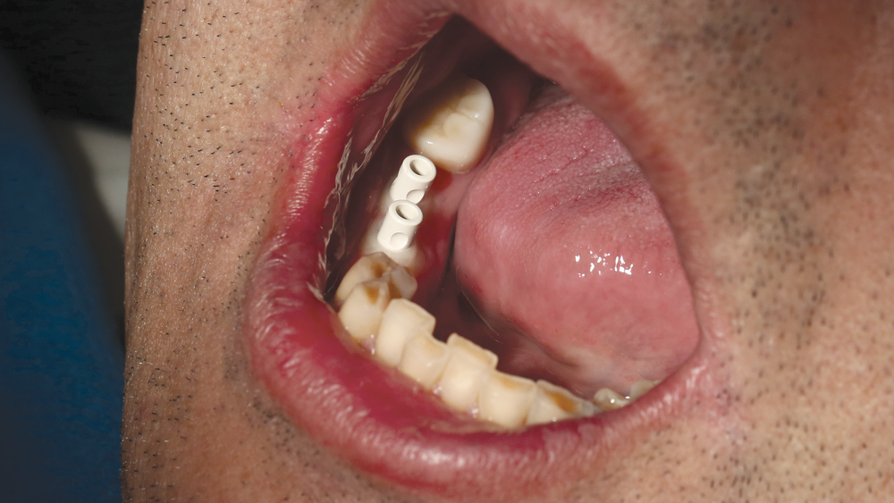
Figure 17: Scanning abutments were connected to the implants so a digital impression could be made. The digital impression technique offers several advantages versus conventional impression-making, including a higher degree of accuracy, reduced lab fees, a quicker turnaround time for the restoration, and a more precise fit.
Figure 18: A series of scans was performed using the TRIOS® intraoral scanner (3Shape North America; Warren, N.J.). After verifying the accuracy of the scan, the case was electronically submitted to the laboratory for fabrication.
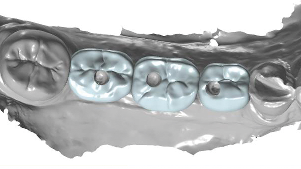
Figure 19: The lab designed screw-retained crowns directly from the digital impression using CAD software. The crowns were designed with a narrow buccolingual width to direct the forces along the long axes of the implants.
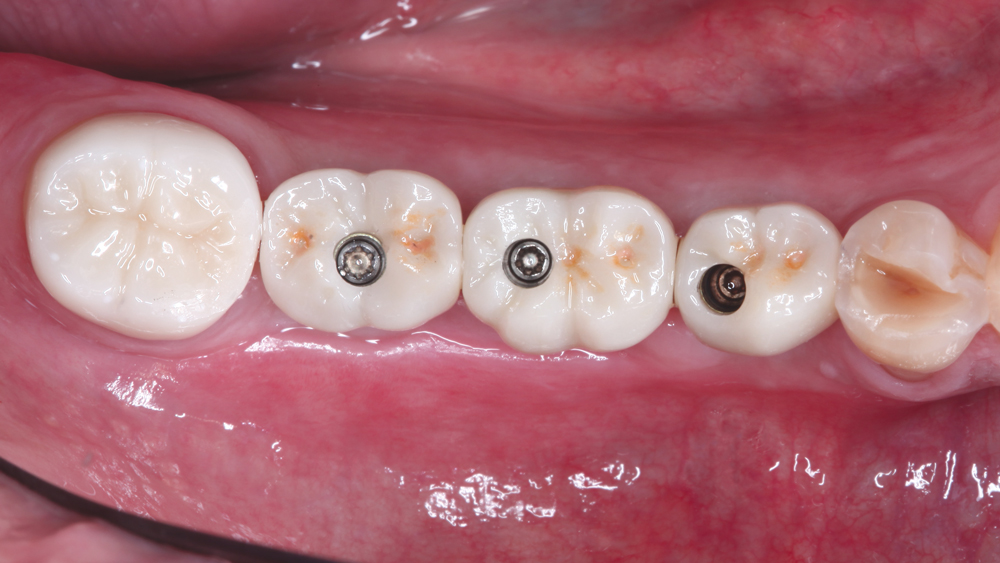
Figure 20: The screw-retained crowns were delivered and immediately established accurate fit, function and occlusion due to the precision of the intraoral scanning and CAD/CAM technology used to produce the restorations. The crowns were fabricated from BruxZir® Full-Strength Solid Zirconia to provide the most durable tooth-shaded posterior restoration possible.
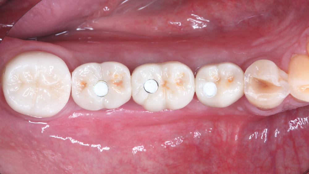 Figure 21a
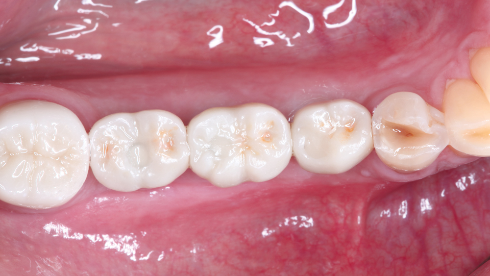 Figure 21b
Figures 21a, 21b: Teflon tape and Camouflage® Universal NanoHybrid Composite (Glidewell Direct) were used to seal the screw-access channels of the crowns.
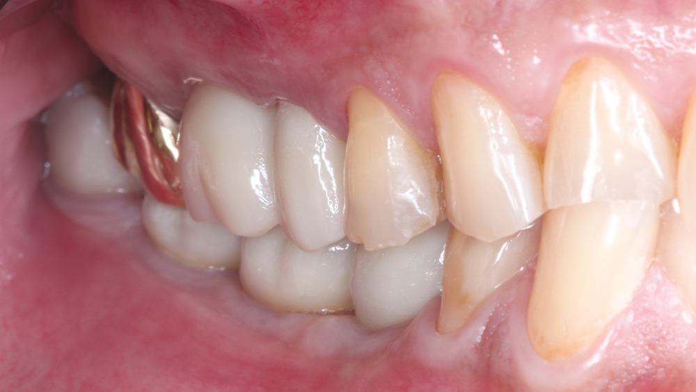 Figure 22a
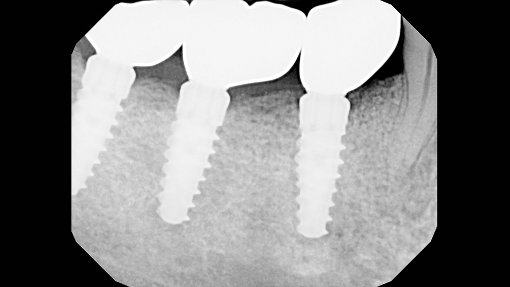 Figure 22b
Figures 22a, 22b: Buccal and radiographic view of the final BruxZir Full-Strength crowns in place, which restored the patient to full dental function and offered an excellent long-term prognosis. The patient was extremely happy with the restoration and the streamlined treatment protocol used to produce it.
CONCLUSION
Implant spacing and selection in the posterior can be determined with confidence by carefully evaluating the patient’s anatomy, performing simple calculations, accounting for any bone deficiencies, and visualizing the prosthetic outcome from the outset. Virtually any obstacle can be overcome with proper treatment planning, especially by taking advantage of the digital tools, implant design innovations, bone grafting materials and prosthetic options available to the modern practitioner.