Photo Essay: Contouring Technique for an Existing Ovate Pontic Receptor Site

January 16, 2014
 image
Michael DiTolla, DDS, FAGD

Despite the increasing availability of dental implants, many patients choose to close edentulous spaces with fixed prosthodontics. When using fixed bridges to replace missing teeth, the dentist should aim at achieving the most esthetic result possible, especially in the anterior region. In the case that follows, the patient already had a Maryland bridge with an ovate pontic receptor site, but it was a little shallow on the facial. He was requesting a replacement prosthesis to fix the recurrent debonding of his resin-bonded bridge. Because I would be replacing his existing bridge, I decided I would also redefine the ovate pontic receptor site that was created when the bridge was first placed 15 years prior.

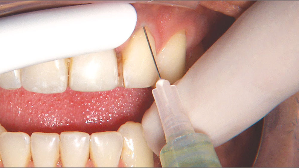
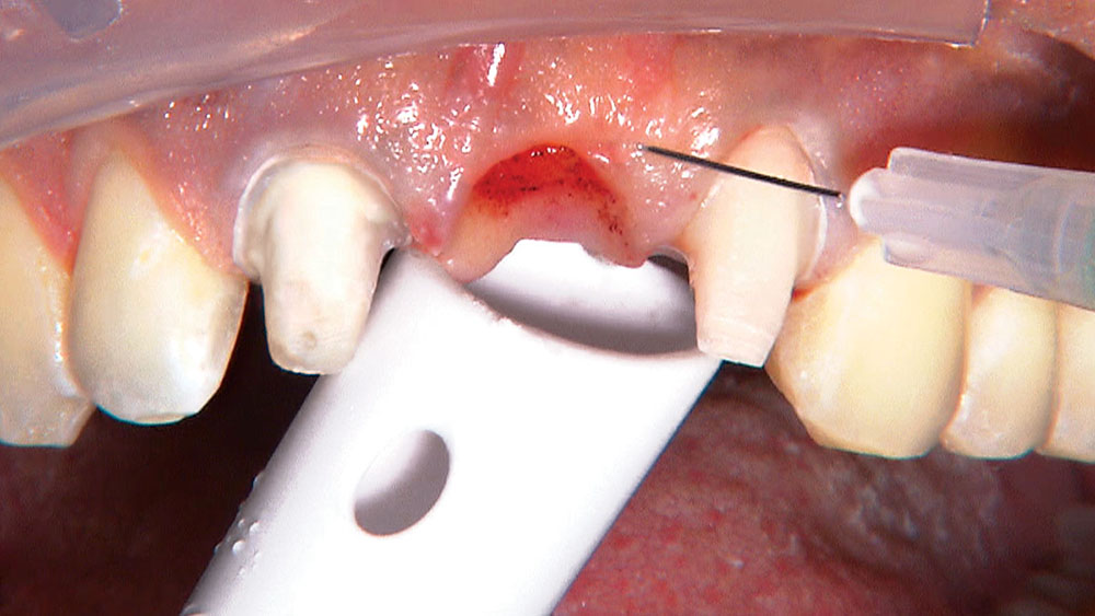
By angling the tip of the syringe toward the tooth as I dispense the gel, I am able to get some of the topical anesthetic into the sulcus.
Figure 1

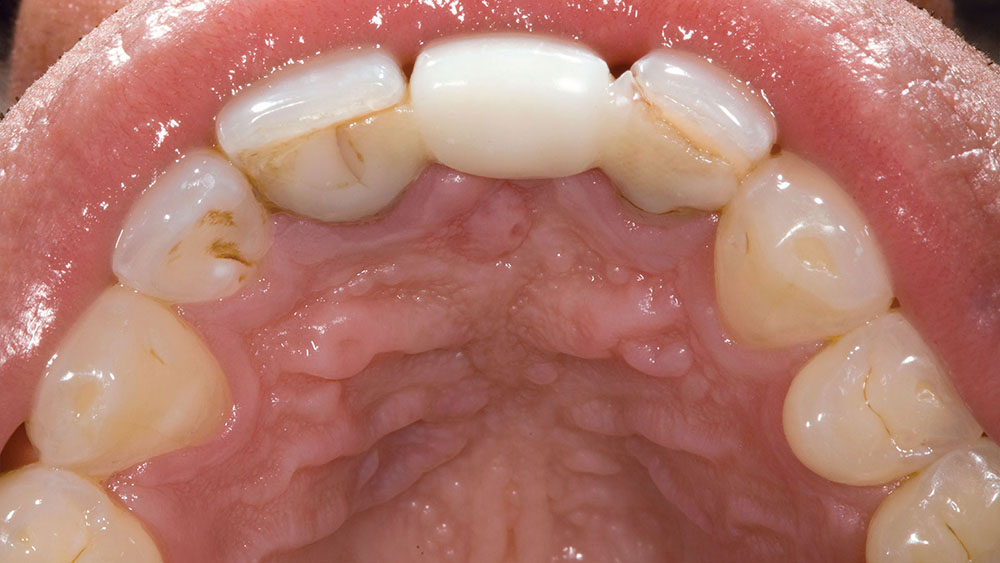
Figure 1: Occlusal shot of the patient’s existing Maryland bridge. This bridge had come off several times and had a tendency to catch food, which was partially responsible for the recurrent decay I found around the wings of the bridge. The patient appreciated the more conservative approach of this resin-bonded bridge, but he was more than ready to change to a traditional 3-unit bridge when I told him that debonding would no longer be an issue.

Figure 2

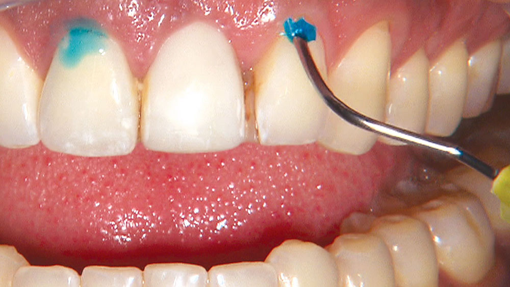
Figure 2: Before I remove the existing bridge, I anesthetize the area by placing PF Lite gel (Steven’s Pharmacy; Costa Mesa, Calif.) directly into the sulcus with the use of an Ultradent syringe. By angling the tip of the syringe toward the tooth as I dispense the gel, I am able to get some of the topical anesthetic into the sulcus. The gel begins to melt as it reaches body temperature, aiding in this process. If I have trouble getting the gel into the sulcus, a long, thin micro-brush, which is typically used to place bonding agent into a canal prior to post cementation, gets the job done.

Figure 3

Figure 3: After placing the topical anesthetic into the sulcus, I use The Wand® handpiece of my STA® (Single Tooth Anesthesia) System unit (Milestone Scientific; Livingston, N.J.) to give pulpal anesthesia via a PDL injection. It is almost impossible to give a painless infiltration on teeth #8 & #10, and patients hate the feeling of their upper lip being numb for hours (I once had a female patient who went to the grocery store after I worked on her anterior teeth, and she told me she was horrified when she got back to her car and saw that her nose was running onto her upper lip and she couldn’t feel it!). This technique allows me to get the tooth and tissue numb without affecting the upper lip.

Figure 4

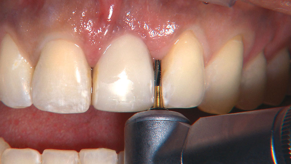
Figure 4: I then use the Razor® carbide bur (Axis Dental; Coppell, Texas) to cut through one of the relatively weak composite wings on the Maryland bridge. This is easy work for this bur, which can be used to cut through most any material except full-contour zirconia. NOTE: If you are trying to cut through a solid zirconia crown, or even a zirconia coping, you will need to use a zirconia-optimized bur (look for the blue stripe on the shank) to get through it efficiently.

Figure 5

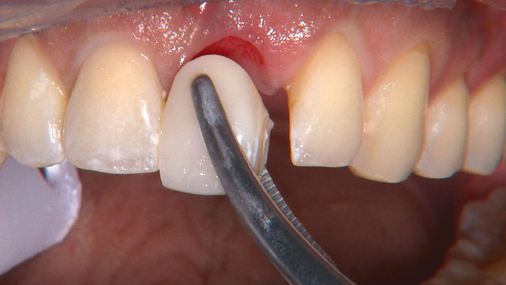
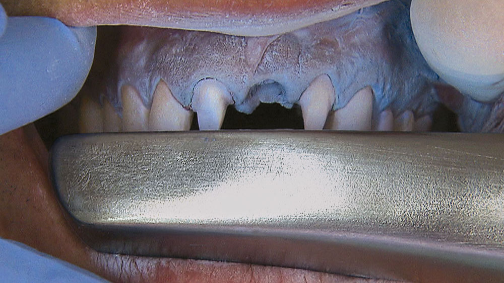
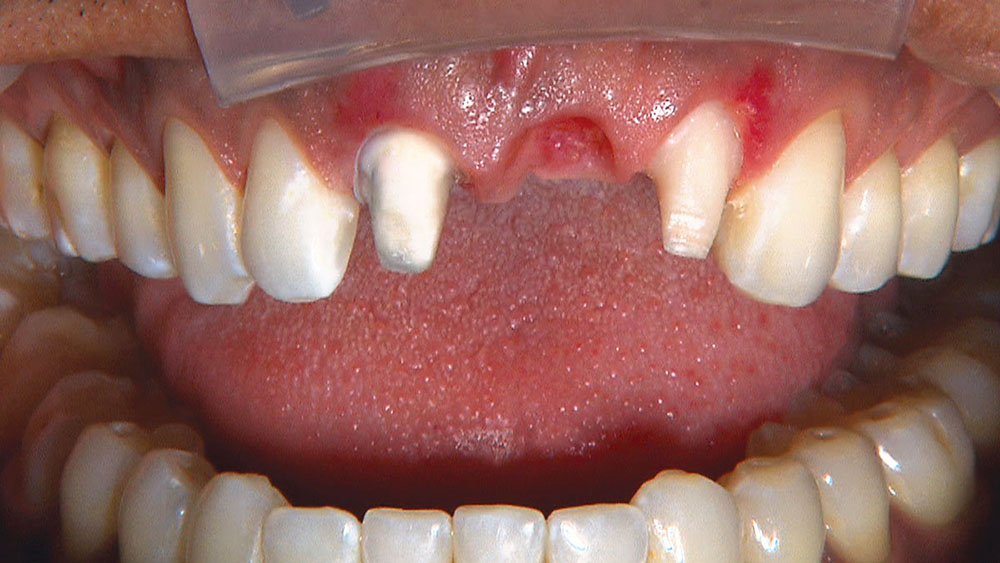
Figure 5: After cutting completely through one wing of the pontic and partway through the wing on the other side, I use serrated forceps to remove the pontic. This is my first view of the tissue under the pontic, and I can see the patient was correct in telling me that the Maryland bridge was placed the day of the extraction. While that is a good technique for developing an ovate pontic receptor site, it can be hit-or-miss when it comes to overall esthetics.

Figure 6

Figure 6: Here, I am breaking through the distal contact on tooth #10 with a #56 carbide bur (Axis Dental). The patient had declined to have an implant placed when he opted for the Maryland bridge because of a relative who had endured a failed implant that was eventually replaced with a bridge.

Figure 7

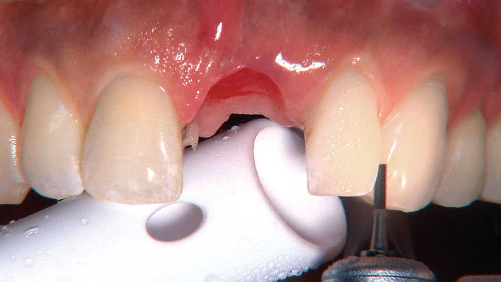
Figure 7: Now I am breaking the distal contact on tooth #8 with the same bur. If we were prepping the adjacent teeth as well (#7 & #11), we would use an 856-025 bur (Axis Dental) because it would break the contacts and prep the interproximal margins simultaneously. We could use an 856-018 or 856-016 diamond (Axis Dental) through the contact instead of the #56 carbide, but the cutting would go more slowly.

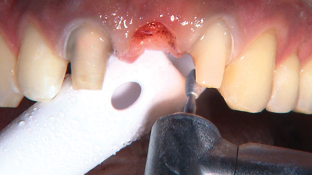
Figure 8

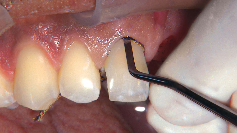
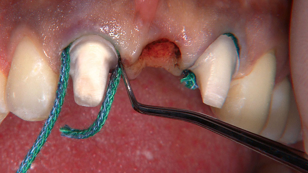
Figure 8: Once I have broken the contacts on teeth #8 & #10, I floss a #00 Ultrapak® cord (Ultradent Products Inc.; South Jordan, Utah) through the broken contacts, pull the two free ends of the cord toward the lingual until the cord is almost tight against the facial surface of the tooth, then use a short, non-serrated cord packer to gently place the #00 cord into the base of the facial sulcus. It’s crucial we get this cord all the way down into the sulcus because this is what determines where the margin of our bridge preparation is going to be.

Figure 9

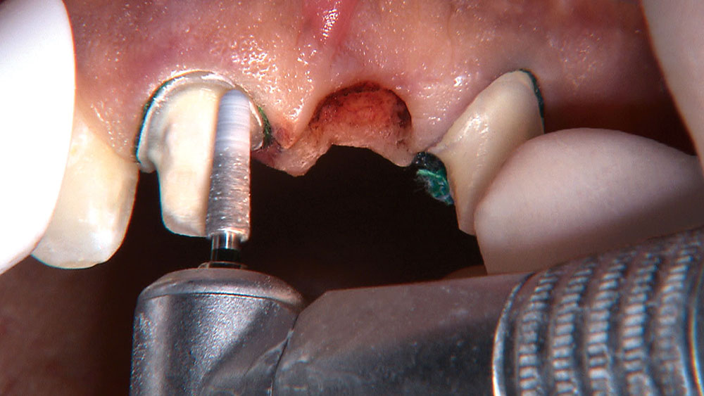
Figure 9: When the #00 cord is in place, it retracts the tissue vertically about 0.5 mm. I use an 801-021 bur (Axis Dental) to prep my margins to this level, so that when the cord is removed and the tissue rebounds, my restorative margins will end up being 0.5 mm subgingival without me ever having to take a bur under the tissue. Taking a bur under the tissue is nearly always problematic, as any gingival bleeding makes capturing a good impression nearly impossible. If I err in any direction, I want to make sure that the round bur is too far from the gingiva, rather than too close, to avoid lacerating the tissue.

Figure 10

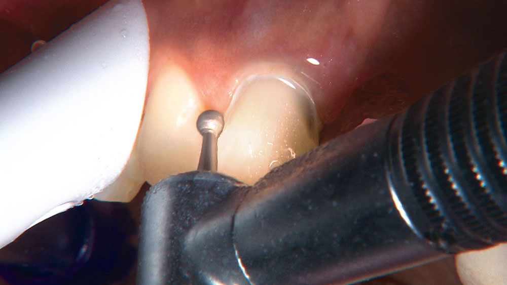
Figure 10: I sink the 801-021 round diamond bur nearly half its diameter into the tooth at the gingival margin, while keeping the shank of the bur as parallel to the long axis of the tooth as possible. This cuts a perfect half-circle into the gingival third of the tooth, creating both a gingival depth cut and the restorative margin. My preps drastically improved once I started prepping the gingival margins at the very beginning of the prep sequence. This technique is called the “Reverse Preparation Technique” because of the fact that the gingival margin is prepped first, rather than last, as I was taught in dental school. While the dental school method may have worked for the top 15% of my class, it didn’t work for me.

Figure 11

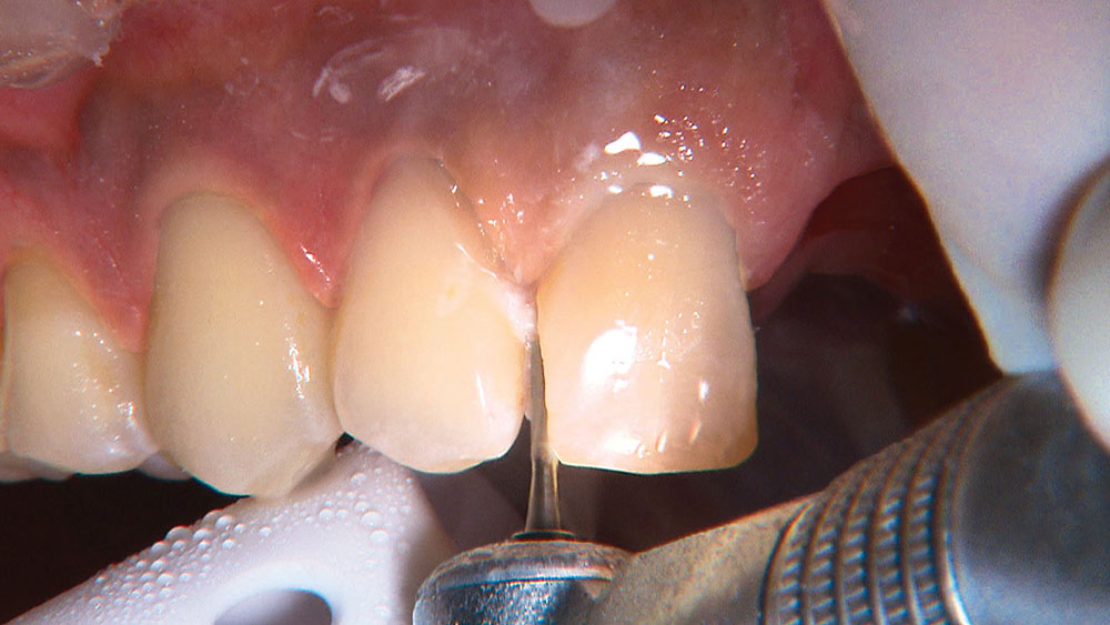
Figure 11: Because the Reverse Preparation Technique is designed to be a universal technique, it uses reduction values that work for both bilayer and monolithic restorations. Here, I am making a 2 mm incisal edge depth cut, which is what PFM manufacturers have requested for decades. This amount of incisal edge reduction also works very well for materials such as IPS e.max®(Ivoclar Vivadent; Amherst, N.Y.) because it provides strength while allowing the technician the option to cut back and layer the incisal one-third for maximum esthetics. Even if I were prescribing a monolithic IPS e.max bridge for this case, I would still want 2 mm of thickness at the incisal edge.

Figure 12

Figure 12: With the 2 mm incisal edge depth cuts in teeth #8 & #10, I am now ready to place my axial wall depth cuts. Keeping in mind the universal dimensions, I place a 1.5 mm depth cut at the junction of the incisal third and middle third. NOTE: Making this depth cut too far to the incisal is preferred over making it too far to the gingival. Properly angling the facial-incisal line back toward the lingual helps ensure the patient can get their lips around the final crown or bridge restoration.

Figure 13

Figure 13: As you can see from this view, the depth-cutting burs are always held perpendicular to the tooth surface on which they’re being used. The shoulders of the depth-cutting diamonds found in the Reverse Preparation Set (Axis Dental) are self-limiting, which means even if you press down on the 1.5 mm depth cutter, it won’t allow you to prep any deeper than 1.5 mm. In dental school, I was taught to place depth cuts with #330 burs that were not self-limiting, which made it difficult to cut through the enamel without going too deep into the dentin. Self-limiting burs allow me to make depth cuts much more quickly, and I don’t worry about inadvertently doing endo on the teeth I am prepping.

Figure 14

Figure 14: Now that the gingival, axial and incisal edge depth cuts are all in place, all I have to do is connect them. These depth cuts provide a map of how to achieve the ideal prep shape. The super coarse 856-025 bur is my favorite for this step. This workhorse bur has a large surface area that allows it to sit on the tooth’s surface without diving into it, which can be especially annoying at the junction of tooth and buildup materials. The large surface area also helps it cut more quickly, and because I know exactly where I’m headed thanks to my depth cuts, I appreciate this reduction in chair time.

Properly angling the facial-incisal line back toward the lingual helps ensure the patient can get their lips around the final crown or bridge restoration.
Figure 15

Figure 15: It’s now time for the lingual reduction. I use a convex football bur in order to create a concave preparation on the lingual that will provide enough space for the lower anterior teeth to function and allow the restorative material to be thick enough to resist fracture. You can use a 1.0 mm depth cutter if you prefer on the lingual surfaces, but I find it easy to verify the reduction visually.

Figure 16

Figure 16: Next, with the speed on my electric handpiece turned down to 2,000 rpm and the water off, I use the 856-025 bur to smooth my prep transitions. I am not planning to take the final impression today because I rarely do when I am doing an anterior esthetic case. In the past, I found myself having to make too many esthetic compromises when I would impress at the prep appointment and seat at the next appointment. I could never be 100% sure how the gingiva would react to the temporaries my assistant would place, and I crave predictable results.

Figure 17

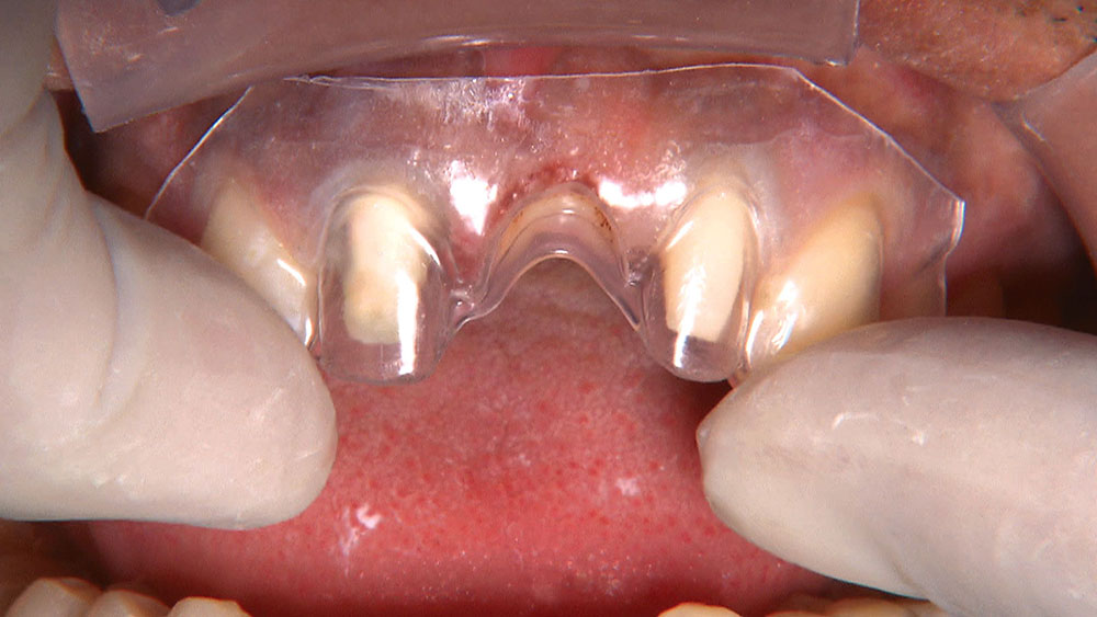
Figure 17: As I will be using a BioTemps® bridge (Glidewell Laboratories; Newport Beach, Calif.) to refine the ovate pontic receptor site, I need to make sure the temporary will seat passively onto the preparations. The prep stent shown here was thermoformed over the model the technician prepped to fabricate the BioTemps bridge. By seating this clear stent onto the preps, I can easily tell whether I have reduced enough tooth structure for the BioTemps to seat passively. The prep stent confirms I have removed enough tooth structure.

Figure 18

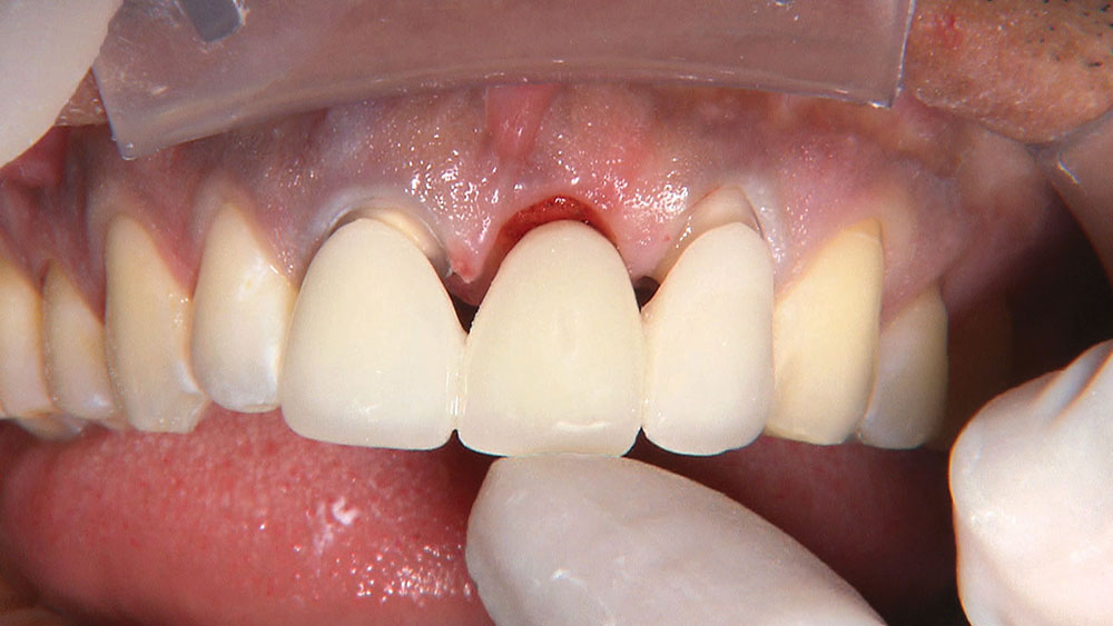
Figure 18: As predicted by the prep stent, the BioTemps bridge is seating passively on the preps; however, there is tissue in the area of the ovate pontic that is preventing it from seating completely. I had the BioTemps technician place the pontic 6 mm into the tissue on the stone model. There is nothing scientific about this 6 mm measurement; I have just established it through trial and error. The pontic on the patient’s Maryland bridge actually looked pretty good, but the facial portion of the pontic was barely subgingival.

Figure 19

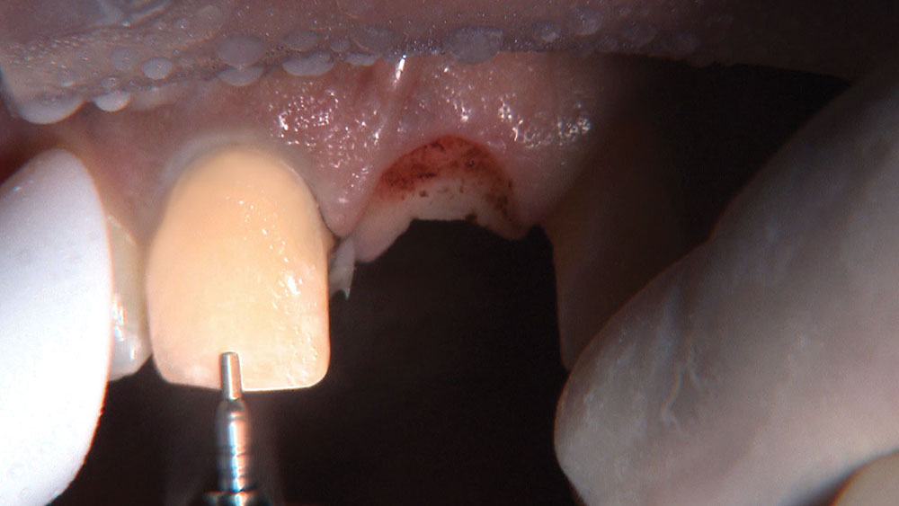
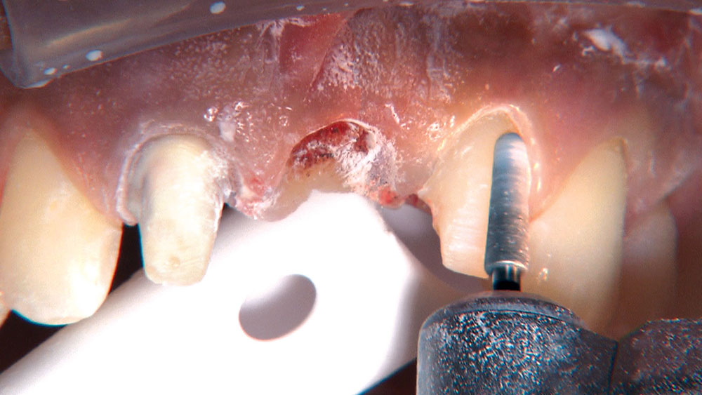
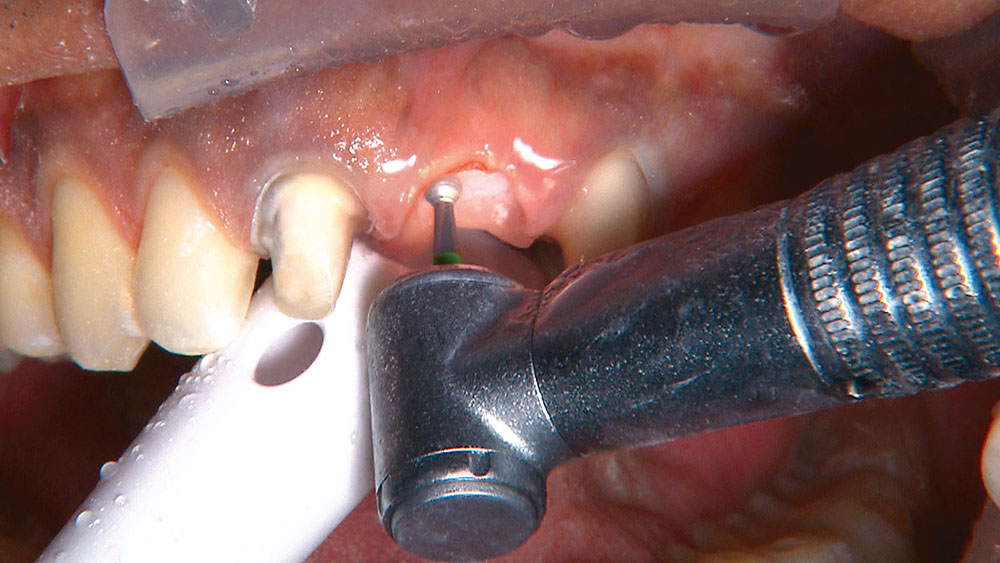
Figure 19: Because I will need to remove some tissue to get the BioTemps bridge to seat, I give some additional local anesthetic (4% articaine). This area is already completely anesthetized, so the main purpose of this extra anesthetic is for hemostasis. When creating ovate pontic receptor sites, you may find that you go all the way through the tissue and into bone. Of course, any time I place a 6 mm pontic into a fresh extraction site, that space in the bone already exists.

Figure 20

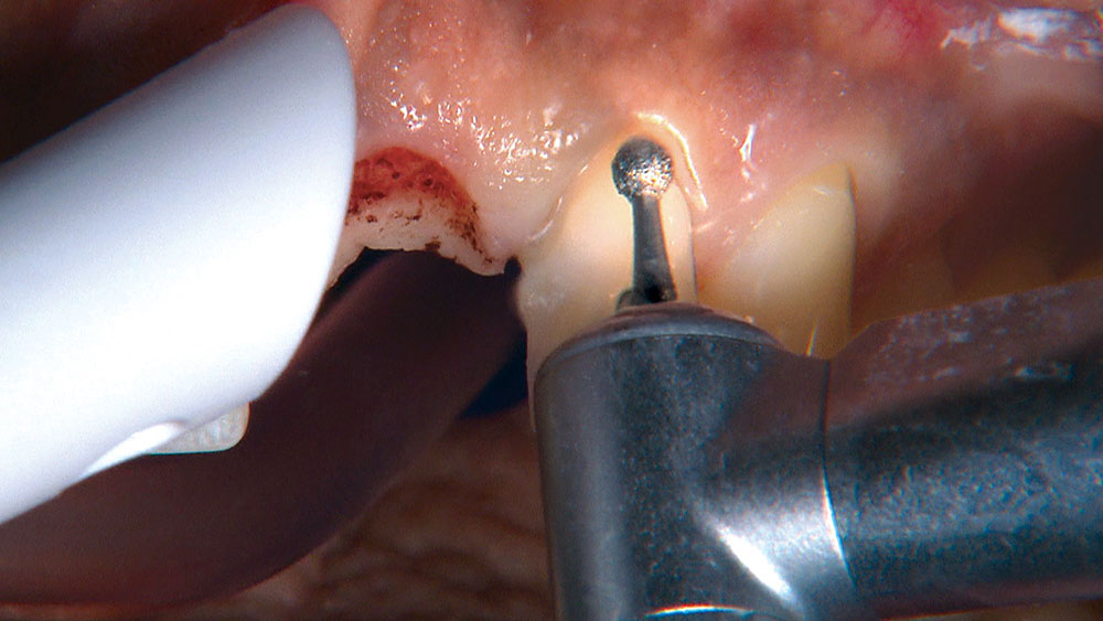
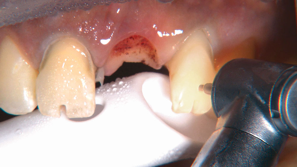
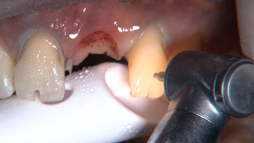
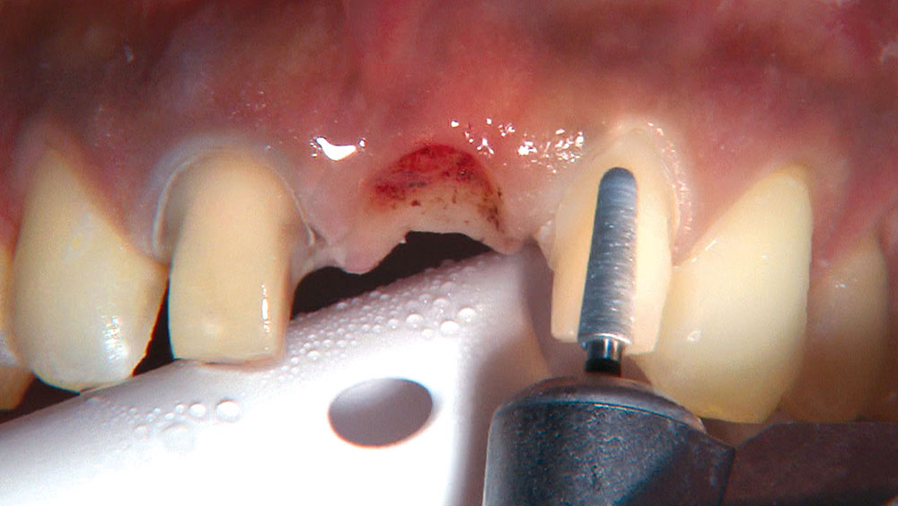
Figure 20: I use a handpiece and bur to recontour the tissue in the receptor site. I used to use a hard-tissue laser for this type of hard- and soft-tissue recontouring, but I found this technique to be too slow. Also, I still experienced bleeding from the gingiva and bone while using the hard-tissue laser, so I didn’t really see any benefit. The periodontists I spoke to indicated that they do the vast majority of their bone recontouring with a handpiece and bur, and I have to agree with them that this is a fantastic way to experience tactile feel during the procedure.

Figure 21

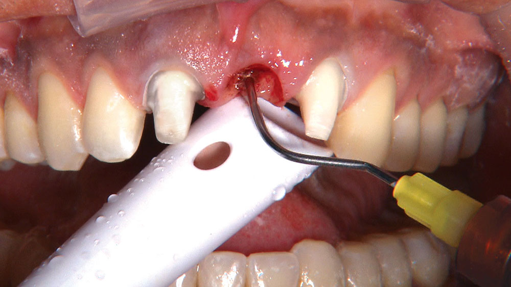
Figure 21: Here, I am applying ViscoStat® (Ultradent Products Inc.). I’m pretty sure this hemostatic agent would stop bleeding from a gunshot wound, but after years of watching medical dramas, it never seems to pop up. One of the keys to being successful with ViscoStat is to remember that you don’t gently dab it on; you will be more successful if you scrub it on. You ask, “How hard?” Good question! According to Ultradent, you should apply the same amount of pressure you would if you were scratching off the silver coating on a scratch-off lottery ticket.

Figure 22

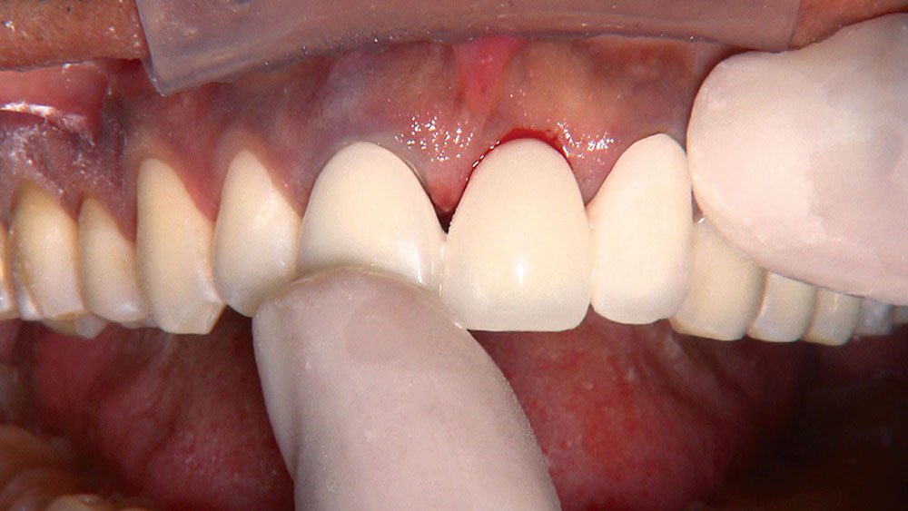
Figure 22: Now, when I try in the BioTemps bridge, I can tell it is seated all the way because the margins are closed on the abutment teeth. Keep in mind that it’s OK to remove more hard and soft tissue than is absolutely necessary to provide room for the biological width. There is no tooth root in the ovate pontic site, so the biological width is not the usual 3 mm from the bone to the free margin of the gingiva; for a pontic, we need only 1 mm of space between the bone and soft tissue.

Figure 23

Figure 23: At this point, I change my mind and decide to take the impression today. This means it’s time to place the top cord: #2E Ultrapak cord (Ultradent Products Inc.). This hollow braided cord is much easier to pack than it may appear to be at first glance. Having said that, there are a few clinical situations where the #2E cord won’t fit, such as lower anterior teeth and some upper bicuspids with minimal attached tissue. In these cases, I will use a smaller second cord, like a size #0 or #1 (Ultradent Products Inc.), or no top cord and a retraction paste like Expasyl® (Kerr Corporation; Orange, Calif.) or Traxodent® (Premier Products Co.; Plymouth Meeting, Pa.) instead.

Figure 24

Figure 24: With the top cord in place, it’s a perfect time to smooth the margins of the preps. Using an electric handpiece, I turn the speed down to 3,000 rpm and the water off, so I can really see what I am doing. Ever since starting to use digital impressions, which magnify your prep about 20 times on the screen, I notice lots of little defects on my preps that can easily be fixed at this point. Fixing any chips and defects means my technician won’t have to guess how to design the margin. Until you try smoothing the prep with the water turned off, you won’t understand just how much of what you were doing was being obscured by the spray. Turning the handpiece speed down to 3,000 rpm ensures that, even with the water turned off, we won’t overheat the tooth.

Figure 25

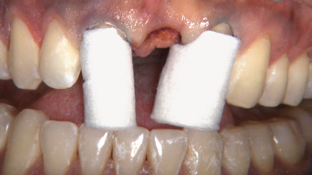
Figure 25: I place two ROEKO Comprecap compression caps (Coltène/Whaledent Inc.; Cuyahoga Falls, Ohio) over the preps for the patient to bite down on for additional hemostasis. We ran out of the ROEKO Comprecap Anatomic compression caps I vastly prefer, so I was stuck using the old style of Comprecaps. If you look at the Comprecap on tooth #10, for example, you will notice that all the pressure is concentrated on the interproximal papillae and none of it is on the facial margin. The anatomical Comprecaps have cutouts for the papillae, providing good pressure all around the free gingival margin without having to worry about blunting the papillae.

Figure 26

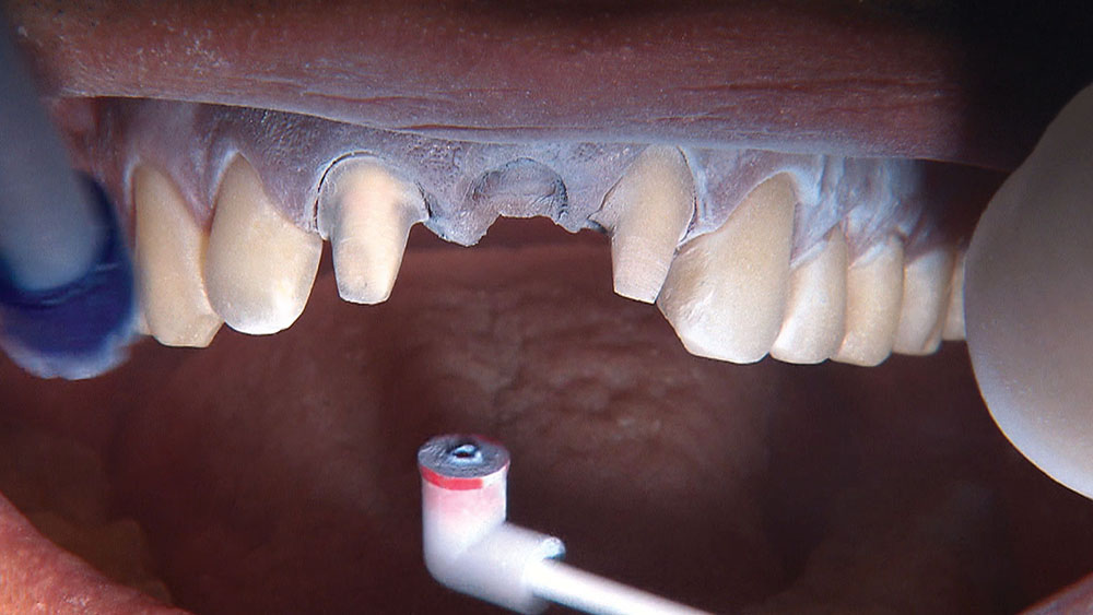
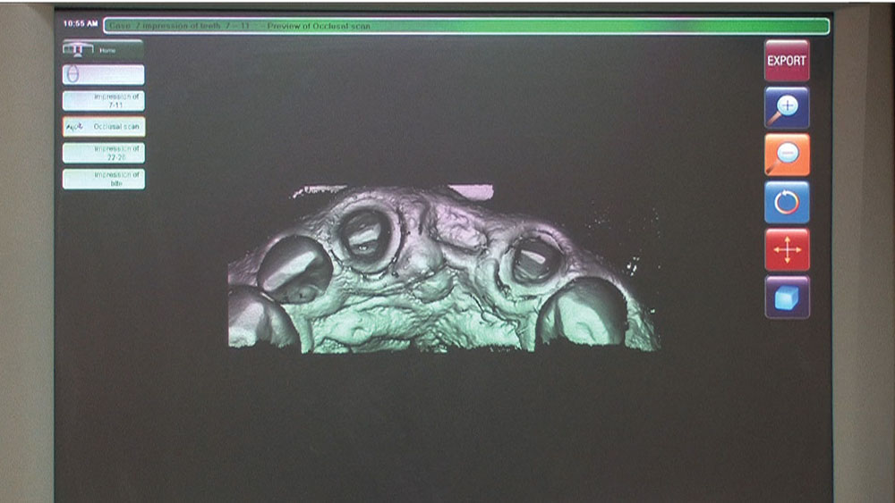
Figure 26: After 8–10 minutes, I moisten and remove the Comprecaps along with the top #2E cord, exposing a wide-open sulcus. At this point, we could take any type of impression and get an excellent result. A good impression is dependent on everything that happens up to the point of taking the impression. The impression itself is basically the report card that lets you know how well you treated the tissue throughout the tooth preparation. Because we will be taking a digital impression using the IOS FastScan® (IOS Technologies Inc.; San Diego, Calif.), contrasting powder is applied.

Figure 27

Figure 27: The IOS FastScan scanning wand contains an intraoral camera that moves back and forth automatically within the head of the unit, allowing me to hold the scanner in place adjacent to the teeth while it captures 40 mm of dentition per second. It takes just a few seconds for the scanner to make a digital image. I then rotate the scanner to the facial to capture that data, and then to the lingual to capture those surfaces. I then ask the patient to bite together, and I scan the bite by capturing the preps and the opposing teeth in the same frame.

Figure 28

Figure 28: The virtual model as seen on the IOS FastScan screen. This is why taking digital impressions will make you a better dentist: Instead of staring into the recesses of a traditional impression, a digital model can now be viewed on-screen. Traditionally, labs have the upper hand in this process because they get to pour up dentists’ impressions in stone and see the actual models, whereas dentists have to judge the accuracy of their impressions before sending them to the lab. Digital impressions flip that scenario around, allowing dentists to view the digital model before transmitting it to the lab.

Figure 29

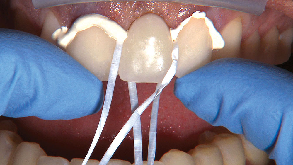
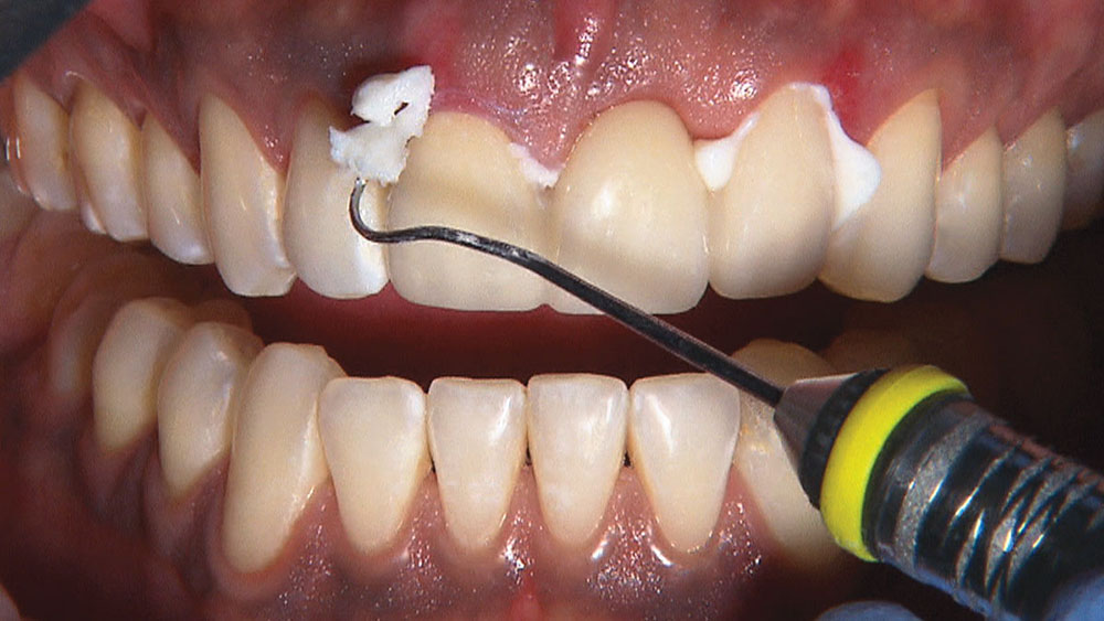
Figure 29: After I capture the digital impression, my assistant relines and trims the BioTemps bridge. Now, her No. 1 job is to make sure she doesn’t leave any remnants of the temporary cement in the freshly prepared ovate pontic receptor site. To achieve this, she places a couple pieces of dental floss into the gingival embrasures of the bridge, fills the bridge with cement and seats it. This allows her to remove all of the excess cement with minimal picking from the explorer in the site of the pontic.

Figure 30

Figure 30: The seated BioTemps bridge. Note the intentional black triangle left between teeth #8 & #9. Black triangles are present between the other teeth, too, but only the one between the centrals is visible from this angle. For years, I tried to make my temporaries look perfect, only to accidentally blunt the interproximal papillae by not leaving enough space for them. At the final seating appointment, the crowns would look great, but the patient would be left with black triangles. Ironically, creating black triangles with the temporary keeps them from happening with the permanent crowns.

Figure 31

Figure 31: After four weeks, we removed the temporary to check the healing of the ovate pontic receptor site. My assistant was able to clean all the cement from around the tissue side of the pontic, so it was healing well. Despite this, the tissue looked a little too immature, and the temporary was put back on for an additional four weeks. After this extended healing period, the tissue is looking healthy enough to proceed with cementation of the final restoration.

Figure 32

Figure 32: After trying in the BruxZir® bridge (Glidewell Laboratories) and checking for fit and function, I use two pinewood sticks to hold the bridge in place while the cement sets, in case there is any soft-tissue rebound. An IPS e.max bridge would have been another option for this case. In fact, if a dentist had called and asked what to seat in a patient like this one, whose previous restorations had not broken or shown signs of moderate to severe wear, I would have recommended IPS e.max. But this patient is getting this bridge for free, so I want to learn something!

Figure 33

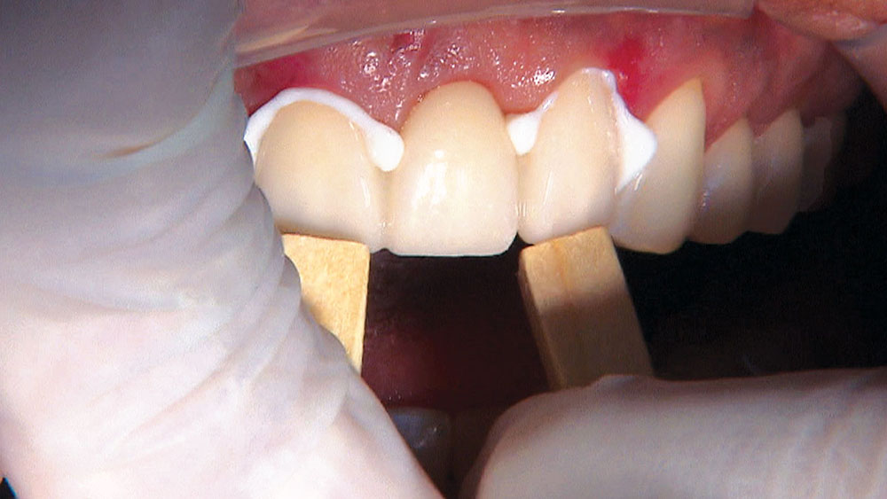
Figure 33: Because we are using Ceramir® Crown & Bridge cement (Doxa Dental Inc.; Newport Beach, Calif.) to cement the BruxZir bridge, we don’t have to worry about decontaminating the internal surfaces of the bridge after they come into contact with the patient’s saliva and salivary phosphates. With other resin-based cements, we would either have to treat the inside of the bridge with Ivoclean® (Ivoclar Vivadent; Amherst, N.Y.), or sandblast it with 50-micron aluminum oxide powder at 35 psi for 15 seconds. The easy cleanup of Ceramir allows us to peel off any excess cement in one piece.

Figure 34

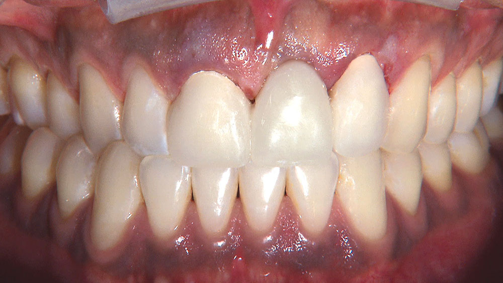
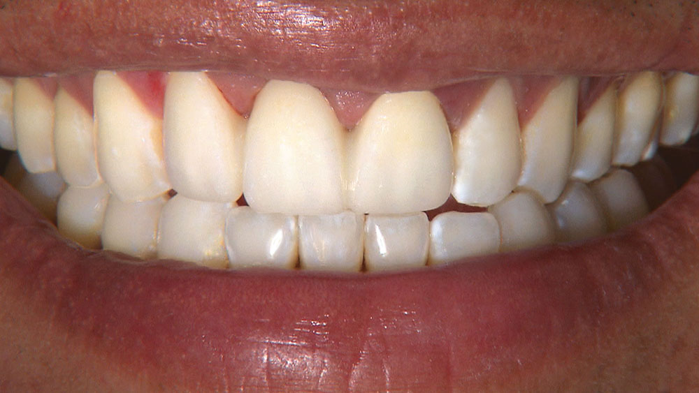
Figure 34: Surprisingly, BruxZir Solid Zirconia is starting to close the gap on IPS e.max as an anterior crown or bridge material, although it won’t be passing it anytime soon. As our lab continues to make it more translucent, I want other dentists to be able to see what it looks like adjacent to natural teeth, which is one of the reasons I continue to use it in the anterior as well as the posterior. For patients with heavy bruxism or those who have fractured traditional PFM restorations, BruxZir restorations are often the best choice.

When creating ovate pontic receptor sites, you may find that you go all the way through the tissue and into bone.

References

  1. de Vasconcellos DK, Volpato CÂ, Zani IM, Bottino MA. Impression technique for ovate pontics. J Prosthet Dent. 2011 Jan;105(1):59-61.
  2. Gahan MJ, Nixon PJ, Robinson S, Chan MF. The ovate pontic for fixed bridgework. Dent Update. 2012 Jul-Aug;39(6):407-8, 410-2, 415.
  3. Alex G. A visual essay. Use of an ovate pontic to achieve optimal aesthetics and integration in the anterior region. Pract Proced Aesthet Dent. 2008 Nov-Dec;20(10):589-91.
  4. Orsini G, Murmura G, Artese L, Piattelli A, Piccirilli M, Caputi S. Tissue healing under provisional restorations with ovate pontics: a pilot human histological study. J Prosthet Dent. 2006 Oct;96(4):252-7.