In this issue:
Accurate Implant Placement: Digital Scanning and Use of Tooth-Guided, Tooth-Supported Surgical Guides
Author

Advances in technology have given dentists a new level of confidence in the placing and restoring of implants. Highly accurate tooth-guided, tooth-supported surgical guides can be created in the “virtual” world and used to accurately place implants.
The case presented in this article will document the use of digital scanning in the process of planning, designing, three-dimensional (3D) printing, and surgical application of merged-file surgical guides.1,2 Further, digital scanning will be used to design and mill all-zirconia body BruxZir® screw-retained crowns with titanium base final implant restorations.3,4 The use of surgical guides has been shown to provide an increased level of accuracy over “freehand” implant placement and even conventional surgical guides.5
CASE REPORTS
A 48-year-old female patient presented with a mandibular right side edentulous area, with a second bicuspid and all molars missing (Fig. 1). The patient reported that she had several failed endodontic procedures as well as a history of “cracked” teeth. The patient expressed great interest in restoration with implants.

In order to properly evaluate her oral condition and develop a treatment plan, a comprehensive assessment was completed. The patient reported a history of bruxism with an otherwise unremarkable medical history. As bruxism has been reported to be one of the most destructive forces on implants,6 this finding was important to take into consideration for the implant treatment plan.
After gathering and assessing available information, the patient appeared to be a good candidate for implant restorations. She agreed to the placement of three implants in the area of #29–31. Following an explanation of the alternatives, benefits and complications, the patient agreed to the proposed implant placement and restoration.
A review of the clinical treatment process can be divided into three areas: implant planning, surgical placement and implant restoration.
IMPLANT PLANNING AND GUIDE DESIGN
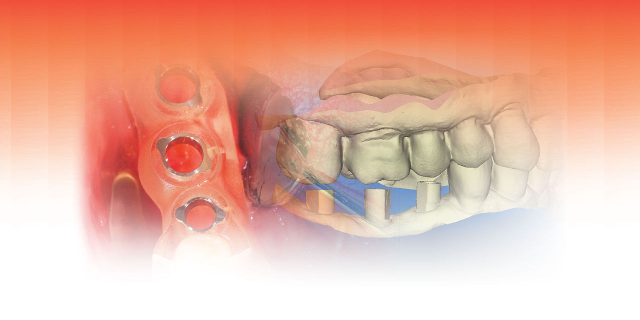
A cone-beam computed tomography (CBCT) scan was used to produce DICOM files to be used for a 3D rendering of the hard tissue of the mandible and adjacent structures; and a panoramic view (Fig. 2) was used to help evaluate the available bone. An iTero® digital scanner (Align Technology Inc.; San Jose, Calif.) was used to produce highly accurate data to replicate the surface morphology of teeth and soft tissue in the area of the implant placement (Fig. 3). The industry-standard STL files7 are derived from the iTero scan and used to create a file that can be merged with the CBCT DICOM files. Open-source STL files (Landlord.stl) are easily exported from the iTero digital scanner.


The STL file merge is important, as the CAD software is used to create an accurate virtual representation surface on which the surgical guide will rest.8 An accurate fit of the surgical guide is necessary to ensure the accuracy of the implant placement. The guide will not be trial-fit on a model but taken directly to the patient’s teeth for surgical application.
Using the planning software, the STL files from the iTero digital scan and the DICOM files from the CBCT scan are merged using common data points. The file merge will then create an accurate virtual rendering on which to plan the desired location of each implant. A software program is used to create a virtual “wax-up” of the morphology of the crown in its desired and optimal arch location. Using the principles of “crown-down” planning, the implant is located such that it best fits available bone and avoids anatomical structures such as the inferior alveolar nerve canal, mental foramen, mylohyoid concavity, etc.
Due to the available bone and location of the anatomical considerations, different implant sizes were used in the planning. Given past implant success, NobelReplace® Tapered Groovy implants (Nobel Biocare; Yorba Linda, Calif.) were chosen for the implant fixtures. A Nobel Narrow Platform (NP) 3.5 x 10 mm was planned for the site of tooth #29, a Regular Platform (RP) 4.3 x 10 mm planned for the site of #30, and an RP 4.3 x 8 mm planned for the site of #31 (Fig. 4).

Upon completion of the planning, the treatment plan was saved on the computer. A dedicated software design program was then used to design the surgical guide. The standard CAD/CAM STL file type was used to send the guide design data directly to the production technology.
The surgical-guide-design STL file was sent to a Stratasys printer (Eden Prairie, Minn.) to be printed three-dimensionally. The 3D printing technology has been used in industry for many years, and dentistry is beginning to realize its many benefits. An FDA-approved material, Med 610, was used as the 3D printing material. With the Stratasys 3D printer, there are different surface texture possibilities for the surgical guide. For example, the exterior may be a glaze or matte finish, the interior a glaze or matte. The surgical guide in this case was clear (Med 610), and was printed to be a matte surface on internal and external surfaces. Metal guide sleeves were inserted into the precisely planned drill-guide holes. The printing-material flash was removed and the guide edges smoothed for use in the mouth.
The 3D printing technology has been used in industry for many years, and dentistry is beginning to realize its many benefits.
The surgical guide was designed with “seating verification” windows so that the clinician could inspect the fit of the tooth-supported guide. These planned cutouts are placed at the marginal ridges to help verify complete seating of the guide.The surgical-guide-design STL file was sent to a Stratasys printer (Eden Prairie, Minn.) to be printed three-dimensionally. The 3D printing technology has been used in industry for many years, and dentistry is beginning to realize its many benefits. An FDA-approved material, Med 610, was used as the 3D printing material. With the Stratasys 3D printer, there are different surface texture possibilities for the surgical guide. For example, the exterior may be a glaze or matte finish, the interior a glaze or matte. The surgical guide in this case was clear (Med 610), and was printed to be a matte surface on internal and external surfaces. Metal guide sleeves were inserted into the precisely planned drill-guide holes. The printing-material flash was removed and the guide edges smoothed for use in the mouth.
SURGICAL PLACEMENT
After application of Benzocaine topical, two 1.7 cc carpules (34 mg) of 2% Lidocaine (1:100,000 epinephrine) were given to the patient. Local anesthesia was administered as a standard inferior alveolar nerve block with a long buccal supplementary infiltration. A solution of Listerine® mouthwash (Johnson & Johnson; New Brunswick, N.J.) was used to soak the tooth-guided, tooth-supported surgical guide. A full-thickness flap was created to ensure adequate attached gingiva surrounding the implants, as well as to inspect the implant head location to the crest of the alveolar ridge (Fig. 5).
The surgical guide was placed, and using the marginal-ridge inspection windows, full seating was verified (Fig. 6). The guide actually fit with a nice “snap.” The drill sequence was started at the #29 site with the NP counter-bore drill bit. This drill helps center the 2.0 mm twist drill that is used next in the sequence; it must be used with a collimator device made to fit the NP metal ring in the surgical guide. The 2.0 mm twist drill was measured and drilled to the planned depth, again using a precise collimator in the guide tube (Fig. 7). The final NP drill was the full depth and size NP tapered drill. These three sizes complete the drilling for the NP tapered implant.


The osteotomy sites of #30 and #31 were planned for 4.3-mm-diameter RP tapered implants. The drilling sequence for this size Nobel guided drill is as follows: (1) RP counter-bore (no collimator), (2) 2 mm twist drill used with an NP collimator, (3) NP drill used with an RP collimator, and (4) RP final drill (no collimator).
Using the Nobel implant placement tool on the drill handpiece, each implant was sequentially placed as follows: The implant placement tool apical shoulder was left about 1.0 mm short of the surgical guide metal guide ring. The implants were manually rotated to position using the hand torque wrench. The implant was rotated to position so that the orientation dimple faced the buccal, indicating the “V” of the internal tri-lobe of the NobelReplace Tapered Groovy implant oriented in the conventional manner. A value of 35 Ncm was recorded for each implant.
Next, 5.0 mm (height) healing abutment cylinders were screwed into place with hand tightening (Fig. 8). The 4-0 chromic gut sutures were used to close the tissue. A post-op periapical radiograph was taken to confirm the full seating of the healing abutments, as well as to confirm the relative implant positions (Fig. 9).


The patient was given post-op instructions and told the expectation was to restore the implants in six months.
IMPLANT RESTORATION
Following a period of six months, the healing abutments were removed and the implant osseointegration was confirmed with 35 Ncm of reverse torque, “counter-rotation.” Inclusive® Clinical Scanning Abutments (Glidewell Direct; Irvine, Calif.) were inserted into the internal Nobel tri-lobes and screwed into place with the integral titanium screw (Fig. 10). After all three scanning abutments were placed, their full seating was verified with a panoramic radiograph (Fig. 11). The iTero scanning unit was used to produce STL files that were then sent directly to the dental laboratory team (Glidewell Laboratories).
A full-arch scan was taken and a precise rendering was displayed on the computer in the operatory (Fig. 12). The clinician may use the many iTero manipulation and measurement tools to evaluate the scan in the virtual world and make real-time adjustments, such as with the eraser tool to re-scan any missing data, without having to re-scan the entire arch. After the scanning was completed, the scanning abutments were removed and the healing abutments were hand-tightened.
The clinician may use the many iTero manipulation and measurement tools to evaluate the scan in the virtual world and make real-time adjustments.
Using the Glidewell CZ software, the screw-retained monolithic zirconia crowns (BruxZir Solid Zirconia) were milled with 5-axis milling machines, and precise titanium bases were milled to be inserted into the crowns. The milled BruxZir screw-retained crowns were fabricated without conventional model verification. The implant crowns had a titanium implant-interface.
As mentioned earlier, the issue of the patient’s excessive occlusal forces with a history of tooth fracture and bruxism were of concern for the success of the implants and their restoration. The lab team was instructed to reduce the buccal-lingual width to about 60% of the original size in an attempt to reduce the occlusal forces. Further, the lab was directed to minimize the occlusal contact to help protect the implants from the bruxism occlusal forces.
In only a few days, the implant crowns were returned from Glidewell Laboratories for delivery. The healing abutments were removed and the screw-retained implant crowns were seated. The titanium retention screws were torqued to 35 Ncm and then the access holes were covered with Teflon tape to protect the screws. Next, a light-cured composite resin (TPH Spectra® Universal [DENTSPLY Caulk; Milford, Del.]) was used to cover the occlusal access holes (Fig. 13).
As the patient’s history of bruxism was a concern, the implant crowns were intentionally designed for a reduced buccal-lingual width, as well as minimal occlusion. The esthetics, crown morphology, contacts and occlusion met the design parameters (Fig. 14). No adjustment was necessary.


An iTero digital scan was taken of the final restoration and opposing arch (Fig. 15) so that a full-arch thermoplastic “occlusal guard” could be constructed on a model printed on a Stratasys 3D printer (Fig. 16). The patient was given instructions to wear the occlusal guard at night in order to help reduce excessive bruxism forces.
DISCUSSION
The excellent outcome for this case offers evidence of the benefits of iTero digital scanning as used in the workflow of implant placement and crown restoration. CBCT DICOM data was merged with iTero open-source digital scan data (STL files) to produce a 3D rendering with tooth morphology so accurate that a tooth-supported, tooth-guided surgical guide could be designed directly in a 100% digital environment that would fit perfectly in the patient’s mouth without the need for models. Accuracy of the implant placement was extraordinary, as the guide was used for the osteotomy drilling as well as for the direct implant placement.
The final implant restorations were also done in a 100% digital environment without the use of physical models. Intraoral iTero digital scanning of the dedicated “scanning abutments” created STL data that allowed the computer-aided design of milled screw-retained monolithic zirconia crowns with milled titanium bases. This design allowed a titanium interface, implant crown to implant head. The restorations, made in a digital environment without models, produced remarkable accuracy and fit that required no adjustments.
CLOSING COMMENTS
More development needs to be done, but DICOM and STL file-merge software now offers practitioners a 3D rendering on which to plan the implant crown position in relation to the implant location, and offers a software platform on which to directly design the tooth-guided, tooth-supported surgical guide. The individual customization features of 3D printing technology facilitates the guide design data (STL files) and can be sent directly to the Stratasys 3D printer to print the surgical guide. The accuracy of implant restoration technology is further evidenced in the conjunction of iTero digital scanning with Glidewell dedicated scanning abutments to design and mill the implant restorations, in this case requiring no contact or occlusal adjustment for the screw-retained implant crowns.
It is anticipated that there will be improvements in scanning technology and the accompanying design software, as technology is rapidly advancing. Improved accuracy and consistency can be expected to elevate the confidence level for both implant placement and restoration. The future is bright for the development of accurate implant placement with tooth-supported surgical guides, as is seen with this case example.
Dr. Jones currently serves as director of the department of continuing education at Virginia Commonwealth University School of Dentistry, and is an adjunct faculty associate professor in the oral maxillofacial surgery department. He maintains a private practice in Richmond, Virginia. He can be reached at perry@drperryjones.com.
DISCLOSURES
Dr. Jones reports no disclosures.
References
- ^Misch CE. Dental implant prosthetics. St. Louis: Mosby; 2004.
- ^Jones PE. Creating surgical guides using CBCT and intraoral scanning. Inclusive. 2012;3:83-90.
- ^van der Zel JM. Implant planning and placement using optical scanning and cone beam CT technology. J Prosthodont. 2008;17(6):476-81.
- ^Jones PE. Milled Modeless Crowns. Dental Product Shopper. August 2012. Available at: http://dentallearning.net/articles/milled-modeless-crowns. Accessed Aug. 20, 2013.
- ^Farley NE, Kennedy K, McGlumphy EA, Clelland NL. Split-mouth comparison of the accuracy of computer-generated and conventional surgical guides. Int J Oral Maxillofac Implants. 2013 Mar-Apr;28(2):563-72.
- ^Johansson A, Omar R, Carlsson GE. Bruxism and prosthetic treatment: a critical review. J Prosthodont Res. 2011 Jul;55(3):127-36.
- ^Chua CK, Leong KF, Lim CS. Rapid prototyping: principles and applications. 2nd ed. River Edge (NJ): World Scientific Publishing; 2003. Rapid prototyping data formats; p. 237-94.
- ^Frisardi G, Chessa G, Barone S, et al. Integration of 3D anatomical data obtained by CT imaging and 3D optical scanning for computer aided implant surgery. BMC Med Imaging. 2011;11:5.