Photo Essay: Hiding a Darkened Root in the Anterior with an IPS e.max® Crown and Veneer

June 3, 2015
 image
Michael DiTolla, DDS, FAGD
Photo Essay: Hiding a Darkened Root in the Anterior with an IPS e.max® Crown and Veneer

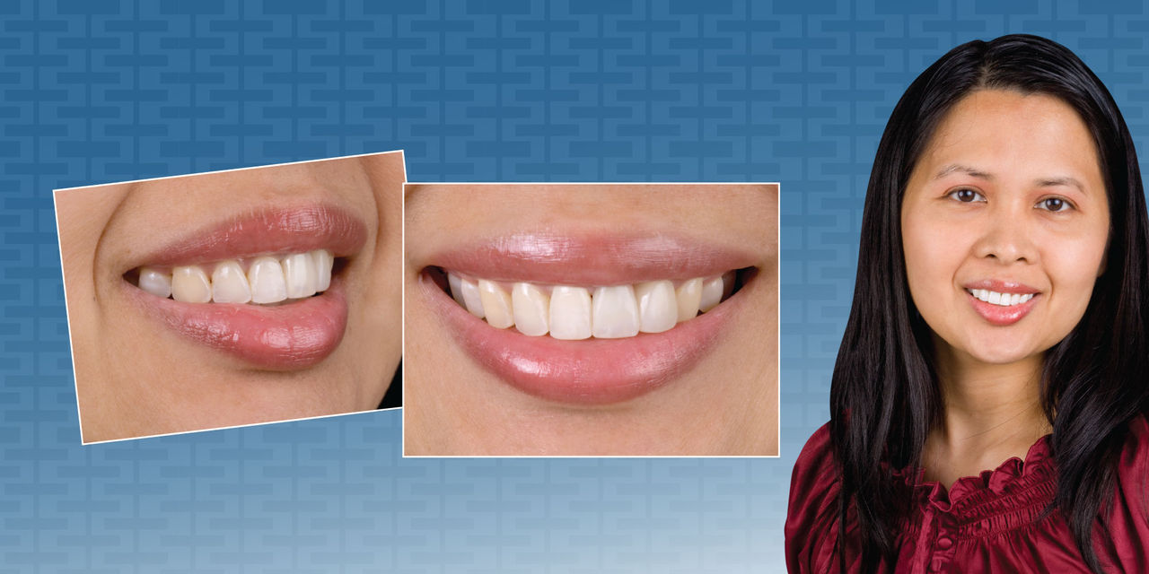
Given the increasing popularity and higher esthetics of monolithic materials, restorations can look much more lifelike than they have in the past. In the case that follows, I replace a chipped zirconia crown that was lacking in esthetics and not comparable with the translucency standards of today’s zirconia. Thanks to IPS e.max® (Ivoclar Vivadent; Amherst, N.Y.), I was able to deliver a restoration that matched the patient’s existing central incisor a lot better than that zirconia crown.

Figure 1

Figure 1: This 39-year-old female came to the office unhappy with the existing crown she had on tooth #9. The tooth had been endodontically treated 10 years ago; then four years ago, a zirconia-based crown was placed as a replacement for the PFM crown that had been there prior to the endo, but had subsequently chipped. Since then, there had been some recession of the gingiva, which had exposed the darkened root from the endo.

Figure 2

Figure 2: The patient’s other main complaint was the shape of tooth #10 and the resultant gingival embrasure between the two teeth. I told her that if we hoped to close the large black triangle between #9 & #10, we would have to place a restoration on tooth #10 as well; hopefully, a conservative no-prep veneer.

Figure 3

Figure 3: This lateral view shows the zirconia crown on tooth #9 to be too bulky in the gingival third and longer than tooth #8 at the incisal edge. We can also see just how high the value is on this zirconia crown, a problem that occurred with many of these crowns until the zirconia oxide was made more translucent.

Figure 4

Figure 4: With the retractors in place, we can see the gingival recession that has occurred, exposing the dark root of the endodontically treated tooth. Thankfully, when she smiles, she doesn’t show this area of the tooth. I always feel like there should be a “high smile-line” surcharge on those cases because the degree of difficulty goes up.

Figure 5

Figure 5: This left lateral view clearly shows the extent of the black triangle between teeth #9 and #10. It’s apparent that we aren’t going to be able to close this with just a crown on tooth #9, hence my suggestion of the veneer on #10.

Figure 6

Figure 6: In fact, many times when I am doing a single crown on tooth #8 or #9, I will suggest a no-prep veneer on the other central at the same time. It frees up the technician from the near impossible task of matching the adjacent natural tooth and ensures the centrals will match.

Figure 7

Figure 7: This occlusal view is imperative when deciding what type of veneers to place on a patient. Dentists frequently send me smile pictures and ask if the patient needs no-prep or minimal-prep veneers, but you can’t have that discussion without an occlusal picture. In this case, tooth #10 is an excellent candidate for a 0.3 mm no-prep veneer.

Figure 8

Figure 8: A close-up look at the zirconia-based crown on tooth #9 shows that the incisal edge is longer than tooth #8, and the overall shape of the crown does not match #8 either. We decided to use an all-ceramic crown without a substructure to replace the zirconia crown in hopes of getting a better match, and I opted to use an IPS e.max Press Impulse crown and veneer.

Figure 9

Figure 9: I am going to give local anesthesia because I’ll be placing two retraction cords. I used to try to avoid local anesthesia when possible, but since developing a painless injection technique, it’s not an issue. Here, I place PFG Lite (Steven’s Pharmacy; Costa Mesa, Calif.) topical anesthetic onto wet mucosa for 45 seconds and then rinse it off.

Figure 11

Figure 10: After the PFG Lite has been rinsed off, I use the STA® (Single Tooth Anesthesia) System (Milestone Scientific; Livingstone, N.J.) at the slowest speed to deliver the Septocaine® (Septodont; Lancaster, Pa.). After about 20 seconds, I switch the STA System to a faster speed, as the patient is already anesthetized in that area. This is the fastest way to give a painless injection.

Figure 11

Figure 11: You can make the task of cutting through zirconia much easier by having some ZIR-CUT™ Burs (Axis Dental; Coppell, Texas) on hand. It is much easier to cut through the zirconia coping with an electric handpiece because of the additional torque. Regardless, make sure you try to cut through it with a soft touch. As the bur cuts through the last of the zirconia, you will inadvertently cut into the tooth if you have too much pressure on the handpiece.

Figure 12

Figure 12: The crown is popped off with the Christensen Crown Remover (Hu-Friedy; Chicago, Ill.). If a crown has been cemented, it will usually come off in two pieces. If it has been bonded instead, it usually comes out in four pieces and sometimes needs to be cut through like enamel. My bottom line is to cement whenever you can and bond only when necessary.

Figure 13

Figure 13: With the crown off, we can evaluate the prep. It is slightly overtapered in the incisal third, the mesial is slightly underprepared in the gingival third, and the distal margin is slightly overprepared in the lingual. That being said, the prep is still acceptable if we clean up the margins and get a great impression.

Figure 14

Figure 14: Prior to margin refinement, we place an Ultrapak® #00 cord from Ultradent (South Jordan, Utah) as our bottom cord in the Two-Cord Impression Technique. Because this cord will be in place during the rest of the procedure, there is no epinephrine or any medicaments placed on this cord. We floss the cord into the distal; no packing instrument is used.

Figure 15

Figure 15: We then grab the other end of the #00 cord and floss it into the mesial portion of the sulcus. We try to use an instrument as little as possible so we don’t cause any bleeding at this point. Once this cord is in place and we are packing the top cord, we can safely use an instrument without bleeding.

Figure 16

Figure 16: We then grab both ends of the #00 cord on the lingual with cotton pliers and pull them lingually until the cord pulls loosely against the facial surface. You could do this by hand, as I used to until I read that latex powder on retraction cords may inhibit the set of impression materials (although I have not seen proof of this).

Figure 17

Figure 17: We use an instrument on the facial surface to pack the cord into the sulcus because we don’t have a choice. However, by having the interproximal areas already flossed into place, it makes it much easier to pack the cord atraumatically. If needed, the ends of the retraction cord on the lingual can be pulled again if you left too much slack on the facial.

Figure 18

Figure 18: The two ends of the cord are cut with scissors on the lingual so that when they are packed into the sulcus they will butt up against each other and not overlap. If you compare this figure to Figure 13, you will see the tissue has been retracted approximately 0.5 mm so that when we drop the crown margin to the gingival margin, it will end up being approximately 0.5 mm subgingival when the cord is removed.

Figure 19

Figure 19: Using an 856-025 bur (Axis Dental), the margin of the restoration has been dropped to the gingival margin. When dropping margins on cases like this, make sure to keep the axial walls in the gingival third nearly parallel without undercutting them. As the incisal third is overtapered, we can gain some retention and resistance in the gingival third.

Figure 20

Figure 20: The occlusal view of the completed preparation. The distolingual is still overprepared, as it was when we removed the existing crown. However, the rest of the margin has been made more uniform through the use of the fine-grit 856-025 bur. If the post had been inadequate, I would have removed and replaced it and built the tooth up.

Figure 21

Figure 21: The size #2E cord is the top cord in the Two-Cord Impression Technique, and it is also an Ultrapak cord from Ultradent. Because the #00 cord is in contact with the inflamed base of the sulcus, there is no bleeding when this cord is placed. The “E” in #2E stands for epinephrine, which is infused in this cord. A plain #2 cord is also available, if you prefer. A loose end of the #2E cord is visible to facilitate easy removal.

Figure 22

Figure 22: A ROEKO Comprecap anatomic from Coltène/Whaledent (Cuyahoga Falls, Ohio) is placed on the preparation to keep pressure on the gingiva and to keep the cord in place. These Comprecaps really come in handy when you are impressing teeth that you shouldn’t be because the gingiva is thrashed, namely posterior teeth with broken cusps that have been packing food for a few months.

Figure 23

Figure 23: After 8–10 minutes, the top cord is removed. If there had been bleeding at the gingival margins prior to cord packing, it would be a good idea to rewet the top cord before pulling it. This was a tough picture to take — I was trying to show how open the sulcus gets from using the two-cord technique. It is visible on the lingual.

Figure 24

Figure 24: A Clinician’s Choice anterior QUAD-TRAY™ (New Milford, Conn.) was used to make this impression. Today, I believe an impression has to have material beyond the gingival margin to be acceptable. If the impression ends at the gingival margin, it is unacceptable. Years of being at the lab have shown me this is true.

Figure 25

Figure 25: Tooth #9 is an IPS e.max Press Impulse crown. In this case, it did a great job of blocking out a dark root and a gold post. It is notable that IPS e.max has no understructure, yet it can still be cemented conventionally and block out dark stump shades — something not possible with IPS Empress® (Ivoclar Vivadent), for example.

Figure 26

Figure 26: The left lateral smile shows that my laboratory technician, Cindy, did a nice job of closing that huge black triangle between teeth #9 & #10. By doing this, we did make the tooth larger than the average lateral incisor, but then again, the patient’s main complaint was the black triangle.

Figure 27

Figure 27: The right lateral smile shows that the contours of both the crown and the no-prep veneer are acceptable. This is the view that really shows if we have achieved a nice facial profile or if the restorations look bulky, which can easily happen with no-prep veneers.

Figure 28

Figure 28: The incisal view shows the facial profile of teeth #9 & #10 are acceptable. Restored teeth always have a tendency to be larger than their unrestored adjacent teeth, but these two teeth are fairly close in size, even though #10 is a no-prep veneer.