Photo Essay: Providing Implant Treatment and Protecting Dentition with an Astron Occlusal Splint

December 18, 2015
 image
Anamaria Muresan, DMD, ME, CDT
Providing Implant Treatment and Protecting Dentition Main Image

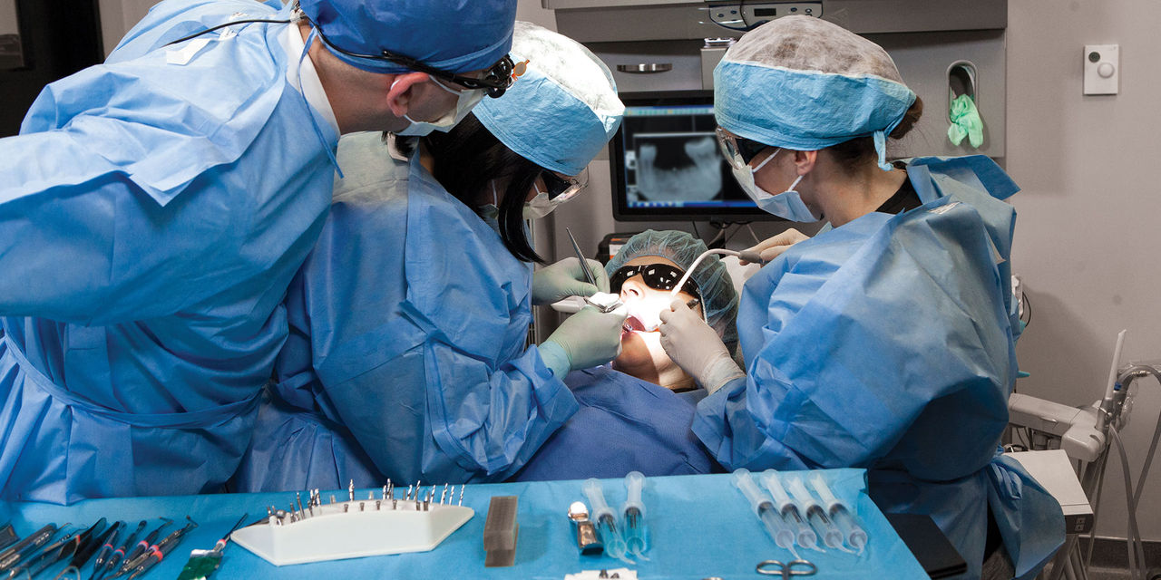
When faced with partial edentulism cases complicated by bruxism, clinicians’ treatment plans necessarily broaden beyond the mere placement of implants. Their armamentarium needs to acquire an ally that can defend the restoration against these excessive forces, and occlusal devices such as bite splints can fill the role. This photo essay, which is Part 2 for detailing this case, shows how implant treatment fit the patient’s need to restore function and esthetics; during and after treatment, an Astron bite splint continued to be the occlusal device of choice. (Find Part 1 here.)

Figure 1a
Figure 1b

Figures 1a, 1b: A 39-year-old female patient presented for implant treatment to replace tooth #30, which had been extracted due to excessive caries. Previously, a removable partial denture was prescribed to maintain function and interproximal and interocclusal space. Figure 1b shows there is adequate bone width and height to place an implant. A single-stage surgical protocol was treatment planned, and the implant procedure was performed according to the following steps.

Figure 2a
Figure 2b

Figures 2a, 2b: Utilizing cone-beam computed tomography (CBCT) scans to acquire 3D images, I am able to accurately measure the height and width of the bone and choose the exact implant size that I want to use. Before placing the implant, I am able to visualize vital anatomical structures and have an idea of whether the density of the bone is adequate or if bone grafting will be necessary. In this case, the images showed adequate bone for apical, mesial and distal requirements.

Figure 3a
Figure 3b

Figures 3a, 3b: Using CBCT technology and a radiographic stent helped me gather information about the locations of anatomical structures in relation to the planned implant site. The radiographic stent — made of hard, clear Erkodur (ERKODENT Erich Kopp; Pfalzgrafenweiler, Germany) — was fabricated to be 2 mm thick and include a 3–4 mm drill opening for placing the gutta percha.

Figure 4a
Figure 4b

Figures 4a, 4b: Alveolar ridge measurements using PreXion 3D Viewer (PreXion, Inc.; San Mateo, Calif.) predicted optimal buccal, lingual, mesial, distal and apical implant position. This served to eliminate variables so that the surgery could proceed easily and predictably. A 4.7 mm x 10 mm Inclusive® Tapered Implant (Glidewell Direct; Irvine, Calif.) was used for this case.

Figure 5

Figure 5: Following appropriate anesthesia, a crestal and sulcular incision with mesial and distal vertical release was performed for full-thickness flap elevation.

Figure 6

Figure 6: The initial osteotomy site was prepared with the aid of a surgical stent as reference for proper positioning. A 0.5 mm diameter lance drill was used for initial perforation of the alveolar ridge, followed by a 2 mm diameter pilot drill. The pilot drill and surgical drills that follow have a stepped design and will accommodate the chosen Inclusive Tapered Implant. To widen the osteotomy, I selected the surgical drills by taking into consideration the density of bone at the osteotomy site and the diameter and length of the implant to be placed: 4.7 mm x 10 mm. All of the drills had black-band depth markings designed to help predict where the top head of the implant will reside when fully seated.

Figure 7

Figure 7: To achieve good primary stability upon implant placement, a two-drill sequence was chosen: First was a ∅2.8/2.3 mm surgical drill, followed by a ∅3.4/2.8 mm drill.

Figure 8

Figure 8: To check the orientation of the initial osteotomy, I used a parallel pin. After confirming the proper position, the osteotomy was continued by moving up in size, with a ∅3.4/2.8 mm surgical drill preceding the final drill.

Figure 9a
Figure 9b

Figures 9a, 9b: A ∅4.4/3.8 mm drill was used to create the final osteotomy. After the implant was removed from the sterile vial, it was carefully transported to the prepared site and inserted into the osteotomy using a handpiece implant driver and the handpiece. Note: This implant has an internal hex connection and a 3.5 mm platform; recommended placement is at bone level. The Inclusive Tapered Implant was threaded into the osteotomy at 15 rpm until fully seated. Featuring resorbable blast media (RBM) surface technology, Inclusive Tapered Implants owe their macro surface roughness to being blasted with a soluble calcium phosphate material. This RBM surface is designed to develop successful implant anchorage.

Figure 10

Figure 10: A torque wrench is used to verify primary stability of the implant.

Figure 11

Figure 11: The implant site was prepared for healing by selecting a ∅4.7 mm healing abutment with 3.5 mm platform and 5 mm height. Once the healing abutment was placed, the implant site was sutured closed with simple interrupted GORE-TEX® CV-5 sutures (W. L. Gore & Associates, Inc.; Flagstaff, Ariz.), with plans to remove the sutures after 14 days and allow 12–16 weeks for osseointegration.

Figure 12

Figure 12: A radiograph confirmed proper seating of the healing abutment as well as the positioning of the implant in the alveolar bone.

Figure 13a
Figure 13b

Figures 13a, 13b: The patient was able to continue using her Astron CLEARsplint® (Astron Dental Corporation; Lake Zurich, Ill.) during the healing phase. Two months after delivery of the healing abutment, the patient returned for the final impression appointment, and a photo with a shade tab was taken to help the laboratory match the final restoration to the existing dentition.

Figure 14a
Figure 14b

Figures 14a, 14b: After the healing period of osseointegration, the patient came for her final impression appointment. At this time, the healing abutment was removed and the impression coping was hand-torqued into place. An X-ray was taken to confirm the transfer coping was seated correctly.

Figure 15

Figure 15: Medium- and heavy-body vinyl polysiloxane (VPS) were used with a full-arch closed-tray impression technique.

Figure 16

Figure 16: Due to concerns about the risk of residual cement, a screw-retained crown was prescribed. A recent report1 by the American Academy of Periodontology now includes residual cement as a risk factor for peri-implant disease (peri-implant mucositis and peri-implantitis). Because of the potential role of residual excess cement as an etiologic factor for the development of biological complications around dental implants, screw-retained restorations are my go-to treatment plan when the patient’s anatomy, esthetics or occlusal considerations don’t require the use of cement-retained restorations. Prescribing a screw-retained implant-supported restoration would eliminate the need for luting cements and therefore rule out a potential component cause for implant failures.

Figure 17a
Figure 17b

Figures 17a, 17b: A BruxZir® Anterior crown was chosen due to the material’s average flexural strength of 650 MPa. The final crown was delivered with one tape shim stock out of occlusion. A suitable material was used to cover the screw head and Camouflage® NanoHybrid Composite (Prismatik Dentalcraft, Inc.; Irvine, Calif.) was used to cover the access hole.

Figure 18

Figure 18: This radiograph confirms that the final screw-retained crown seated completely to the implant.

Figure 19

Figure 19: The patient’s CLEARsplint was adjusted chairside to provide ideal fit with her new restoration in place.

References

  1. Rosen P, Clem D, Cochran D, et al. Peri-implant mucositis and peri-implantitis: a current understanding of their diagnoses and clinical implications. J Periodontol. 2013 Apr;84(4):436-43.