Technological Advances in Chairside Milling
In recent years, an alternative to the age-old workflow of ordering lab-produced crowns and bridges has risen in the form of intraoral scanning, digital designing and chairside milling. Advancements made in software, materials and milling machines have enabled the dental practitioner to produce a same-day crown that rivals those produced by traditional laboratory methods. Additionally, many clinicians report that adopting CAD/CAM technology has made them more cognizant of the importance of tooth preparation and tissue retraction in producing quality crowns and bridges.
Case Study
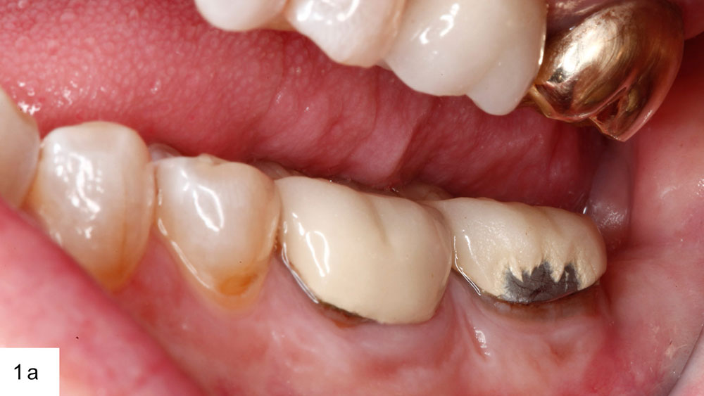
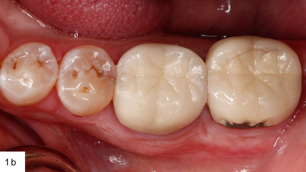
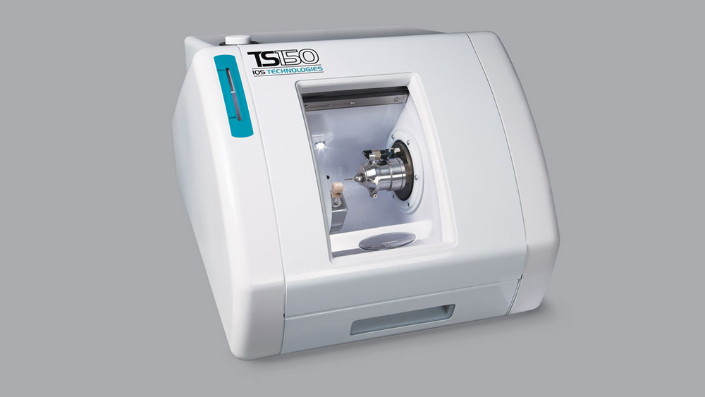
A patient presented with failing PFMs on teeth #18 and #19, with the porcelain veneer sheared off the buccal aspect of #18 (Figs. 1a, 1b). Desiring a restorative material suitable for chairside fabrication, I chose Obsidian® lithium silicate ceramic (Prismatik Dentalcraft, Inc.; Irvine, Calif.), which allowed me to complete the entire case in one visit. Obsidian Milling Blocks are currently compatible with CEREC® milling machines (Sirona Dental Systems, Inc.; Charlotte, N.C.) and the TS150™ from IOS Technologies, Inc. (San Diego, Calif.). For this particular case, I used the TS150 and the associated FastDesign™ software (IOS Technologies, Inc.).
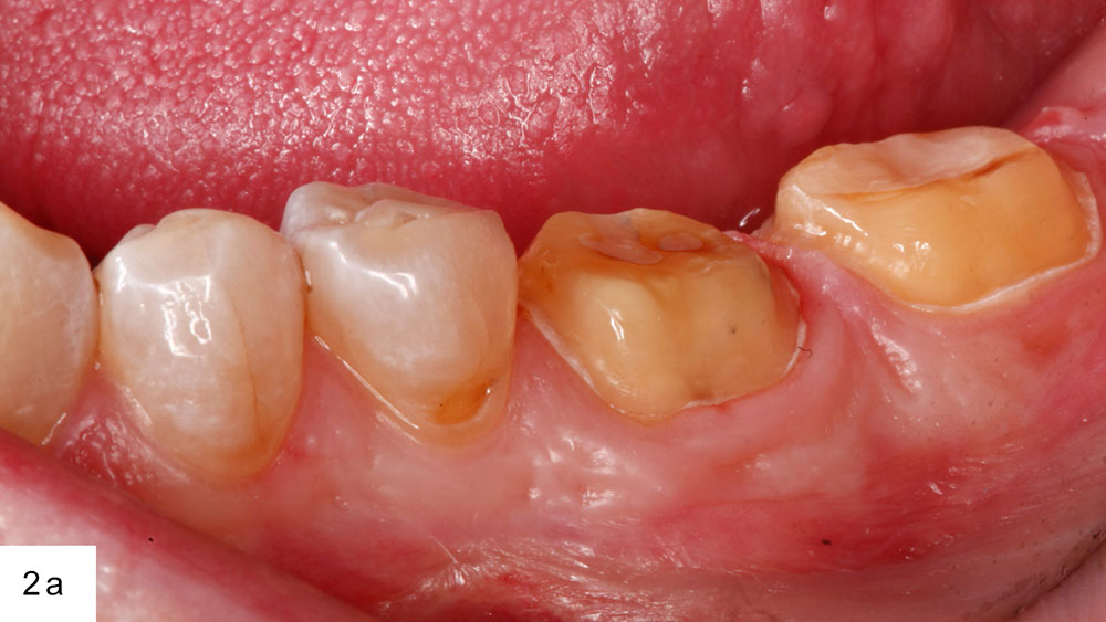
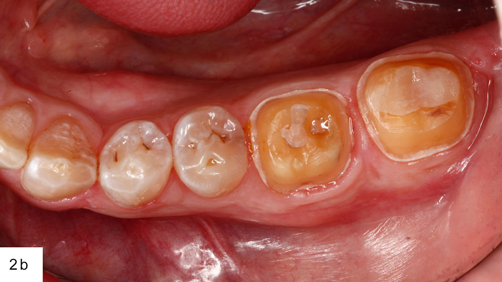
I began the procedure by removing the existing PFM crowns. Although the reduction requirements for PFMs are similar to those of modern all-ceramics, it is common to reduce further on cases that have preexisting dental work to ensure the 1 mm axial and 1.5 mm occlusal material requirements are met. I also rounded the internal angles of the preparations to ready them for a new impression (Figs. 2a, 2b).
Figures 1a, 1b: The preoperative condition. The existing PFMs on teeth #18 and #19 were beginning to fail and were unesthetic.
Figures 2a, 2b: With the PFMs removed and the preparations further reduced, I placed retraction cord to ready the case for impression.
For this case, I used an all-digital workflow, starting with intraoral scanning, then designing the case with software, and finally fabricating via a milling unit. It’s important to note that the fundamentals of achieving a good impression are identical whether that impression is digital or taken with elastomeric materials. The technology simply minimizes the amount of time and the number of potential error-inducing steps between the work you’ve done and the digitization of the same. The requirements for adequate reduction and tissue retraction remain unchanged.
With the preparations finalized, I placed size 000 cord to displace the gingiva apically, followed by size 2 cord to retract laterally. After 5 minutes, the top cord was removed. I verified that the first cord wasn’t adjacent to the margins, and moved to start the scan workflow.
For this case, I utilized the 3M™ True Definition Scanner (3M™ ESPE™; St. Paul, Minn.). The handheld camera has an ergonomic design, along with size and weight similar to a dental handpiece. This smaller camera allows scanning of areas where access may be limited, a problem not often addressed by intraoral scanners.
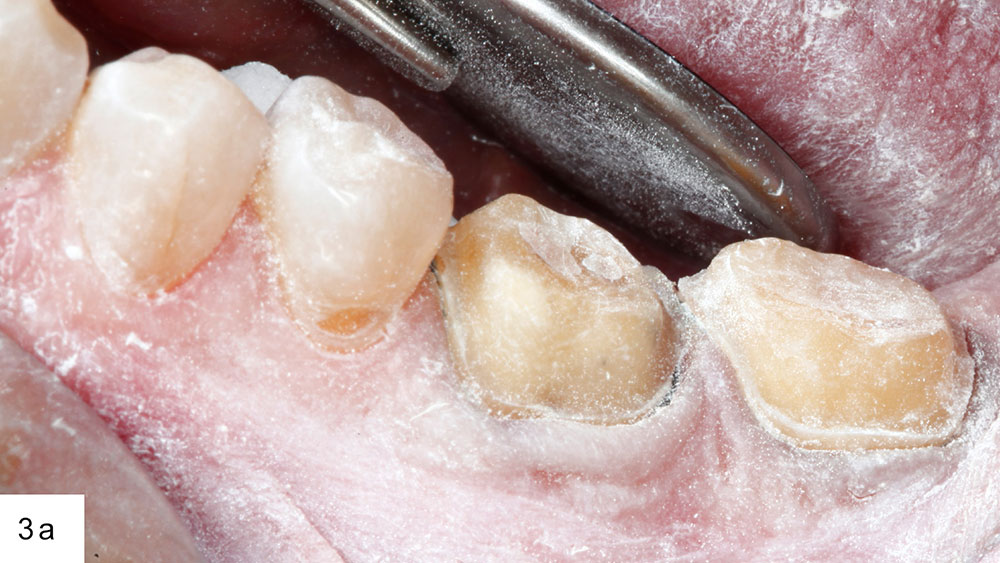
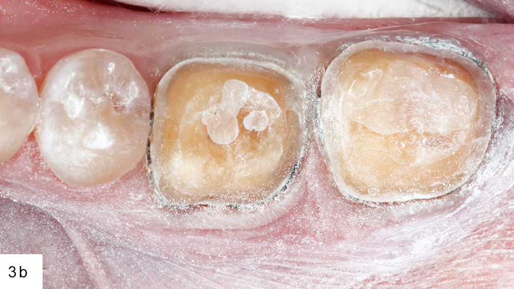
Lower molars tend to be one of the most difficult areas to scan because saliva accumulation can be significant. Intraoral scanning technology requires that the preparations be dry to capture an accurate image. As excessive saliva can lead to distortions, the parameters of the technology dictate proper isolation of the prepared area. To effect this, I placed a cotton roll next to the tongue and had my assistant retract the cheek. The aerosol-applied contrasting agent was sprayed over the prep areas (Figs. 3a, 3b), and then I commenced the scan process.
Figures 3a, 3b: The preparations must be isolated and free from excess liquid prior to applying the contrast spray.
The scanning software is intuitive and fast, and it gives instant feedback on the quality of the impression. If a data set is missed, the clinician can immediately go back to that area and recapture it. For this reason, while clinicians new to intraoral scanning are often in the habit of looking directly in the mouth during the scan process, experienced users learn to watch the screen and move the camera in tandem. This speeds up the process tremendously.
The first area scanned is the occlusal of the prepared arch. Starting here establishes the foundation of the data. With my assistant retracting the cheek while I retract the tongue, I wave the camera over the occlusal, and then rotate the camera to the buccal and lingual to detail those aspects. It is important to cover lower than the height of contour on the adjacent teeth, and to ensure the contact areas are captured completely.
I move from the prepared arch to the opposing, again starting with the occlusal. However, here the lingual aspect is less critical. As long as I accurately capture the occlusal along with the buccal down to the gingival margins, I’ll have a very accurate final result.
The third set of scan data is the bite scan. Prior to actually scanning, I asked the patient to practice his bite. I did this a few times to verify that the patient was able to achieve centric occlusion. If the bite is open or incorrect during scanning, the software won’t recognize that the data is wrong and the restoration may require excessive adjustments upon seating. With the patient in a satisfactory bite position, I scanned the buccal aspect of the bite.
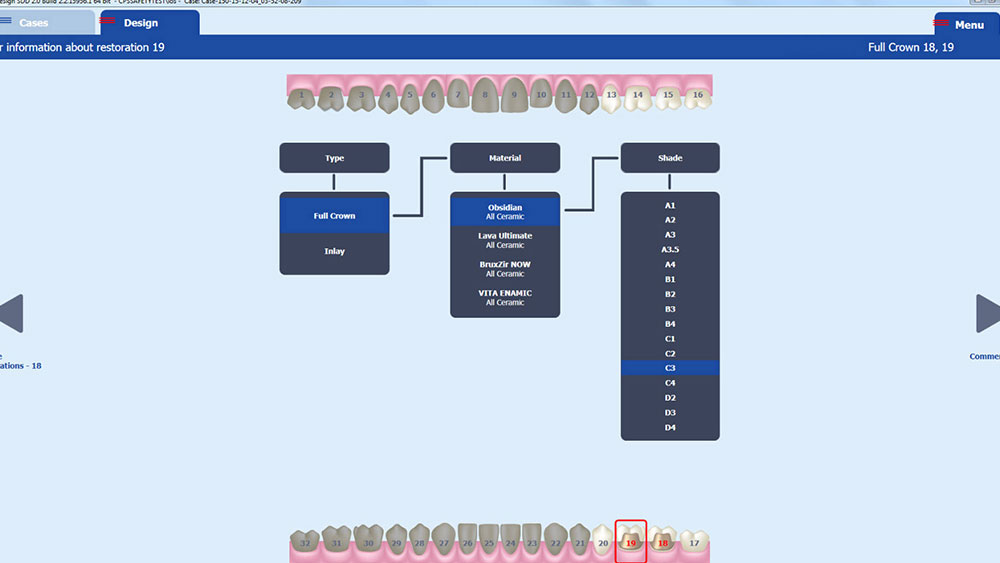
Moving to the design software, I set up the case by indicating which teeth were being prepared, the type of restoration, the desired material, and the shade (Fig. 4). It is of the utmost importance to ensure the correct selection is made at this stage; again, the CAD/CAM technology won’t recognize if details are input incorrectly, just as the mill won’t recognize you’ve inserted the wrong material or shade. Attention to detail will inform every aspect of the digital workflow, from design steps to milling strategy.
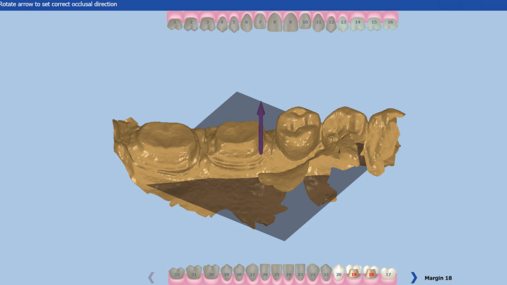
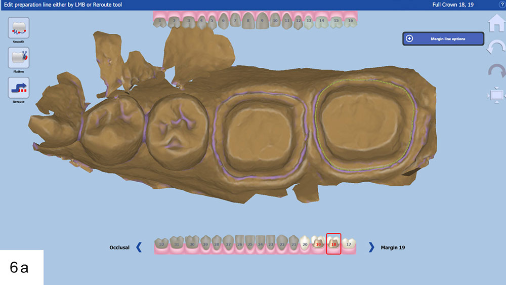
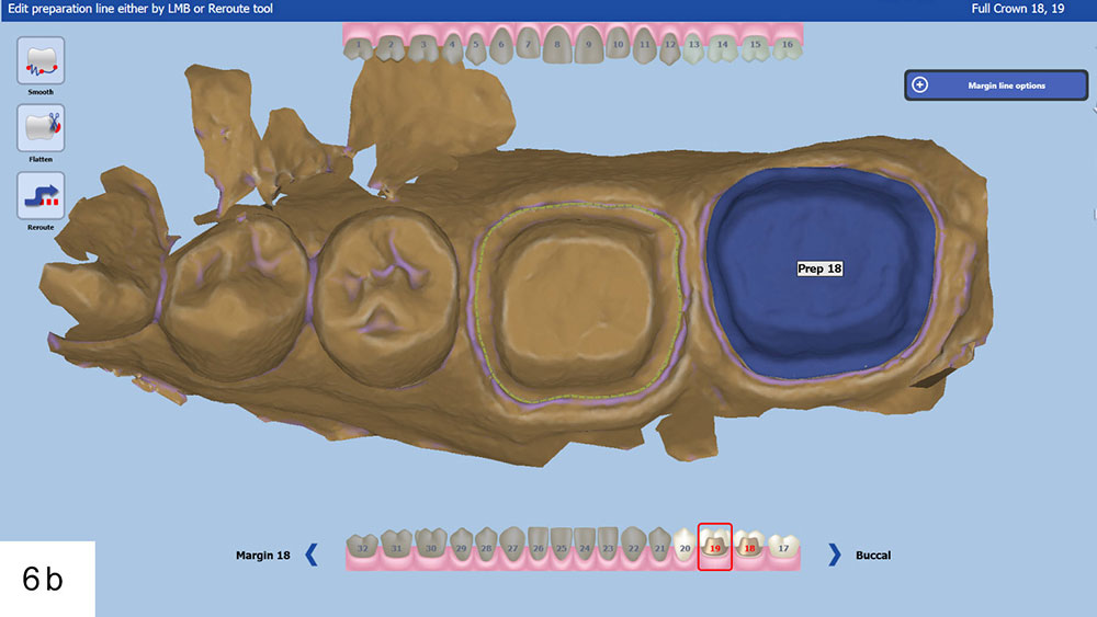
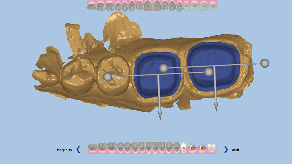
Now in the design stage, I indicated the path of insertion of the restorations (Fig. 5). The software then prompted me to mark the margin for each preparation individually. FastDesign will generate an educated guess at the placement of the margin; however, this can require some further adjusting by the clinician, who moves the margin by positioning digital handles in the correct area to redraw the margin line (Figs. 6a, 6b). When first learning this protocol, the eye-opening experience of realizing just how hard it can be to identify the margin on a digital model can lead clinicians to empathize with the difficulties facing dental technicians. Once I had the margins set, I indicated the buccal direction for each unit (Fig. 7).
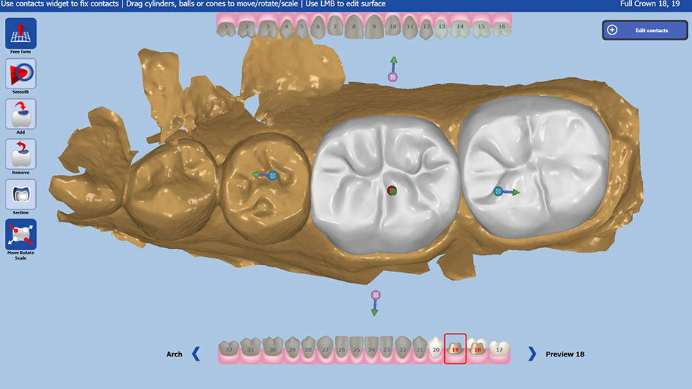
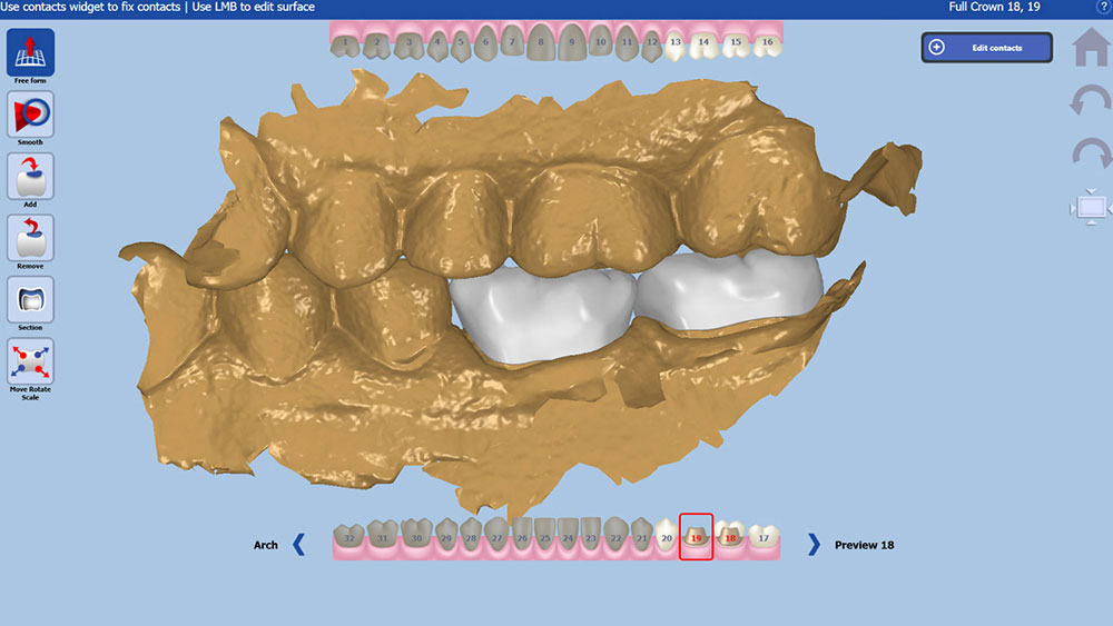
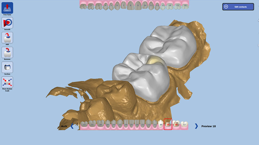
Based on the given information, the software will generate a tooth over the preparation (Fig. 8). The user can reposition the restoration by changing the angulation, rotation and position along the long axis (Fig. 9). This stage is reminiscent of setting denture teeth. Securing the position finalizes the preplanning of the case, resulting in fewer adjustments of the proposed design.
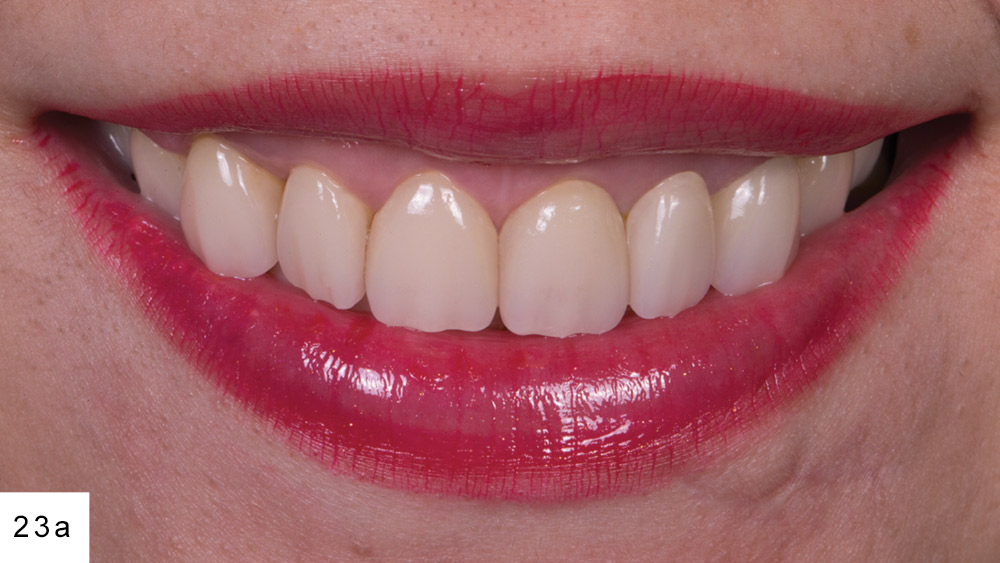
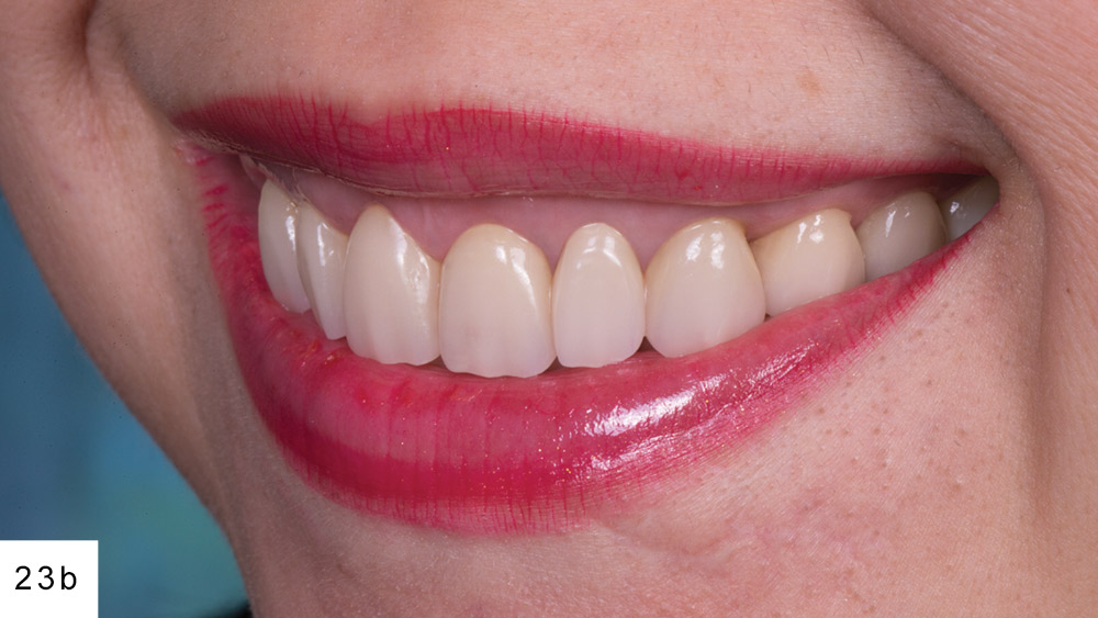
Figures 23a, 23b: The patient’s expectations were exceeded, thanks to her corrective surgical treatment and Obsidian smile makeover.
Figure 4: FastDesign software features case setup with easy-to-navigate dropdown selections.
Figure 5: The first stage of design is indicating the path of insertion.
Figures 6a, 6b: When designing multiple units, margins must be placed on the correct preparation; otherwise, the designs could be reversed.
Figure 7: The software then prompts the user to indicate the buccal direction for each restoration.
Figure 8: Generated teeth are placed somewhat akin to how denture teeth are traditionally placed.
Figure 9: The first step of actual design is to confirm the general position of the restoration.
Once the position has been set, a secondary design toolset appears with two main categories: tools to make large global changes, and tools to make minute, specific changes. It’s recommended to develop a systematic approach to accomplishing this stage of design. After some experience in using the technology, I have developed my own workflow and desired values, greatly reducing the number of adjustments I have to make before seating the restorations.
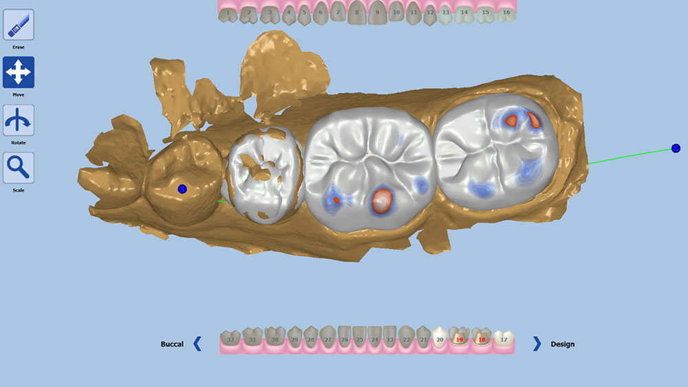
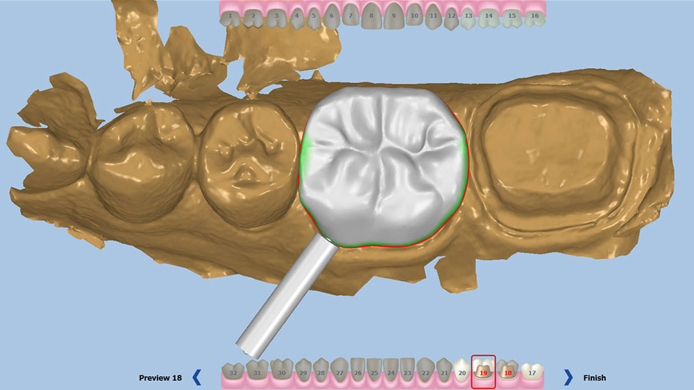
First, I use large global movements to establish the functional position. Second, I toggle the view of the opposing arch, and then reposition the buccal, lingual, mesial and distal aspects to ensure that I have the correct cusp-fossa relationship (Fig. 10). Doing this has largely set the contacts for the case, although I always verify that they are exactly as desired using the software’s measuring tools. If they aren’t located ideally, the proximal anatomy can be adjusted using the general tools. Having solidified the functional anatomy, I then switch to the more specific toolset and make free-form changes to correct the minor esthetic issues with the restorations. These tend to include broadening the contacts, adjusting the marginal ridge position and buccal and lingual contours, and perfecting the cusp shapes. With most of the design finalized, the last step in my workflow is to verify the occlusion and proximal contacts by using the heat map feature. This tool will color the restoration in bright colors in the areas where it interacts with adjacent or opposing teeth. The clinician can program at what dimension each color will appear, making for a very easy visualization of the measurements. With the contacts and occlusion showing the desired colors and numeric value, I’m finished with the design stage (Fig. 11).
The final step prior to milling is placing the sprue for each restoration. It is best to avoid placing the sprue too close to the margins, proximal contacts, or high-esthetic areas. Instead, place the sprue in a position that won’t mar the final appearance and interfere with the proximal contacts (Fig. 12).
Figure 12: It is very important to place the sprues in an area that won’t harm the important functional or esthetic aspects of the restoration.
For this case, I used two Obsidian C3 blocks. The blocks arrive to the clinician in a semi-crystallized state, appearing purple in color. This state is easier for the TS150 mill to work with, and the color is a reminder that these restorations must be crystallized (Fig. 13). In addition, the material can be placed in the mouth; if adjustments are needed, they can be done more easily before the ceramic is in a final state.
The actual milling time for each crown was about 12 minutes. After milling, I used a slow-speed lab diamond bur to finish down the sprue.
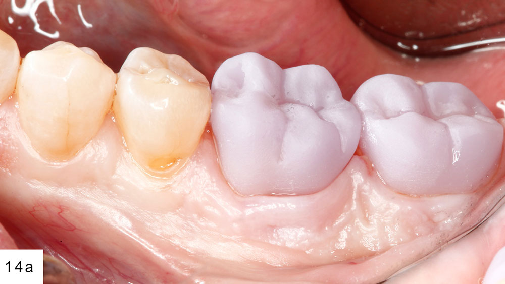
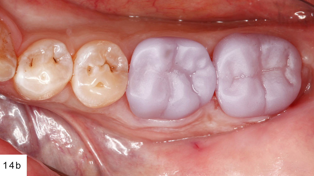
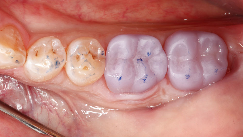
At try-in, the crowns dropped right in (Figs. 14a, 14b). I checked the proximal contacts and marginal seal, and then had the patient bite down gently to verify the occlusion (Fig. 15). A major benefit of the all-digital workflow is that if the clinician acquired the data and designed the restoration correctly, there’s usually very minimal adjustment, if any, needed.
Figure 13: Obsidian restorations are simple to mill with the TS150 due to the semi-crystallized state of the CAD/CAM block.
Figures 14a, 14b: When first milled, Obsidian restorations appear purplish in color, as they are not yet crystallized.
Figure 15: I verified the occlusion with the restorations still in the pre-crystallized state, as adjustments are much easier to make prior to crystallization.
Many chairside milling blocks are monochromatic in nature, whereas real dentition is polychromatic. Because the chairside version of Obsidian requires a crystallization cycle, the clinician has an opportunity to add custom characterization to the crown.
To make my C-shaded blocks appear more natural, I performed a bit of pre-crystallization staining. First, I placed C stain on the middle and cervical thirds of each restoration. On the occlusal table, I used orange stain to create a deep dentin effect. I followed that by using a small amount of brown stain in the primary anatomy. The darker stains add depth, so it’s important to only place dark stains in the deepest portions of the anatomy. Then, I used white to highlight the cusp tips, and the marginal and triangular ridges. Unfortunately, there are no paint-by-number guides or universal instructions to coloring teeth.
The stained restorations crystallize in the oven in a 20-minute cycle. The oven raises the temperature slowly over a period of 10 minutes to 810 degrees Celsius, then holds that for 10 additional minutes. The results are twofold: The restorations harden to full strength, and they change from their purplish color to the desired shade. Once pulled out of the oven, the restorations cool to a safe temperature over a period of about 5 minutes. It is very important not to try to accelerate the cooling with forced air or liquids, as those options can decrease the integrity of the material and even cause catastrophic failure.
Finished restorations in hand, I began preparation for bonding the crowns. I started by etching the internal aspect with hydrofluoric acid to create the micromechanical retention. Then, I applied Monobond® Plus (Ivoclar Vivadent; Amherst, N.Y.) and allowed it to mix on the crown for a period of 60 seconds, air-drying the excess.
To reduce the chance of postoperative sensitivity, I placed GLUMA® Desensitizer (Heraeus Kulzer, LLC; South Bend, Ind.) on the preparations immediately before my bonding sequence. Then, I placed a layer of Scotchbond™ Universal Adhesive (3M ESPE). Even though for the bonding process I would be using RelyX™ Unicem (3M ESPE), a self-adhesive resin cement, studies have shown that applying a bonding agent first can increase the bond strength significantly.
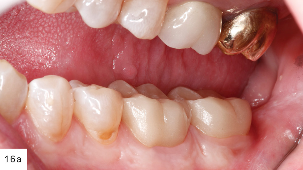
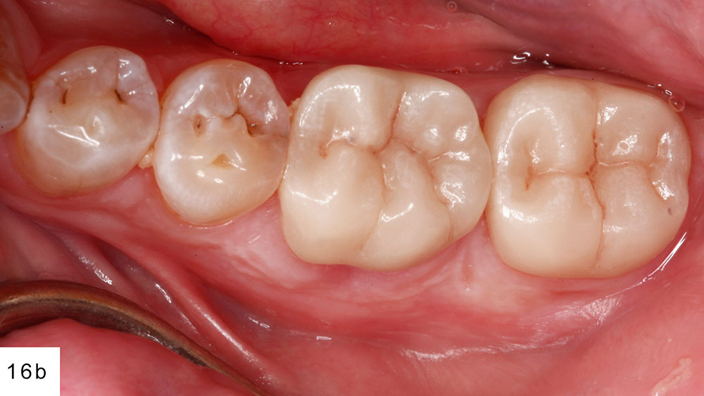
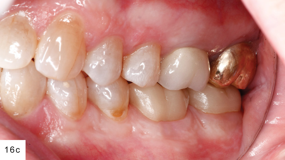
After seating, I tack-cured for three seconds on both the buccal and lingual. This set the cement into a gel state that allowed for easy cleanup. After the cement was cleared and final curing was completed, I re-verified the occlusion of the case. Despite the chairside workflow, there was absolutely no compromise in the fit and finish of these restorations (Figs. 16a–16c).
Figures 16a–16c: Once stained and crystallized, the final restorations were bonded into place. The esthetics are wonderful considering the hour-long workflow.
Conclusion
The all-digital workflow afforded by CAD/CAM technology provides a very effective means of making durable, well-fitting, esthetic single-unit and simple multi-unit restorations. The ability to deliver a crown an hour after preparation is something that patients really appreciate, and there is a significant opportunity to grow your practice around that concept.

