In this issue:
Scannable Abutments: Digital Impressions for Dental Implants
Author
Technological advances are making it easier than ever to practice dentistry in almost every dental procedure.1 The purpose of this article is to increase awareness of a new modality for the restoration of implants by general practitioners and prosthodontists utilizing chairside digital impression systems.2
The conventional protocol for taking an implant impression for crowns & bridges requires a stock or custom impression tray loaded with a polyvinyl siloxane or polyether material that is placed in the mouth to record the position of a properly seated impression coping. This impression is then used to pour a stone model from which the laboratory fabricates the final restoration.
Digital intraoral impressions were first introduced in 1987 by Siemens with the CEREC 1.3 There are now several well-established systems that offer intraoral scanning and digital impression capabilities for the construction of crowns & bridges without the need for impression trays or materials.4,5
For the dentist who needed an implant impression, however, this technology was not yet available. In 2004, BIOMET 3i™ introduced a coded implant healing abutment that provided all of the necessary implant information without the need for impression copings.6 This was proprietary to 3i and more costly than a standard impression, but it was a step in the right direction.
In late 2010, Straumann introduced a scannable abutment called a “scanbody,” which allowed for the taking of a digital implant impression. We needed this option to be available for most commonly used implant systems, however. At this time, Straumann only works with iTero® (Align Technology Inc., formerly Cadent Inc.; San Jose, Calif.).
A dental laboratory in Canada, 5 Axis Dental Design Center, has since taken the concept further by developing scannable abutments that are compatible with implant systems from most of the major implant companies, allowing dentists to submit digital impressions for CAD/CAM design and milling of implant abutments and fixed restorations. However, at the time of this writing, they too can only use the iTero scanner.7
In February 2012, Glidewell Laboratories introduced intraoral scanning abutments under its Inclusive® line of implant products for implant systems from ASTRA TECH, Straumann, Neoss and Zimmer, as well as Certain® (BIOMET 3i™; Warsaw, Ind.), PrimaConnex® (Keystone Dental; Burlington, Mass.), and Brånemark System®, NobelActive™ and NobelReplace® (Nobel Biocare; Yorba Linda, Calif.). These Inclusive Scanning Abutments are also available for the lab’s line of Inclusive Tapered Implants, and they can be used to create digital implant impressions with the available, compatible intraoral scanners, such as iTero, Lava™ C.O.S.® (3M™ ESPE™; St. Paul, Minn.), CEREC® (Sirona Dental Systems Inc.; Charlotte, N.C.), IOS FastScan® (IOS Technologies; San Diego, Calif.) and the soon-to-be-compatible E4D® Dentist (D4D Technologies; Richardson, Texas). Heraeus projects to have a new intraoral scanner, the cara TRIOS®, available this year.
This is a rapidly developing field, and I would not be surprised if in the near future we see a greater number of compatible implant systems and more dental laboratories offering this service.
The following case example demonstrates the simplicity of capturing a digital implant impression using an Inclusive Scanning Abutment and CEREC Redcam acquisition unit with version 3.8 CEREC Connect* software to restore a Zimmer Screw-Vent® implant. However, any of the previously mentioned chairside digital impression systems available today are compatible and can be used for this technique.
Case Presentation
The patient in this case is a 62-year-old male who needed the restoration of a Zimmer Screw-Vent 4.7 wide implant in the area of the right mandibular first molar (Fig. 1). The gingiva had healed around the healing abutment and was ready for the implant impression (Fig. 2).


After removing the healing abutment, I placed the Inclusive Scanning Abutment and finger-tightened it over the implant (Fig. 3). If tissue shaping is required for proper emergence of the final abutment because you did not use a custom healing abutment, you can do it at this time. This will give the laboratory a good idea of the desired emergence profile. The downside is that you will need good hemostasis, as any bleeding will interfere with the impression.


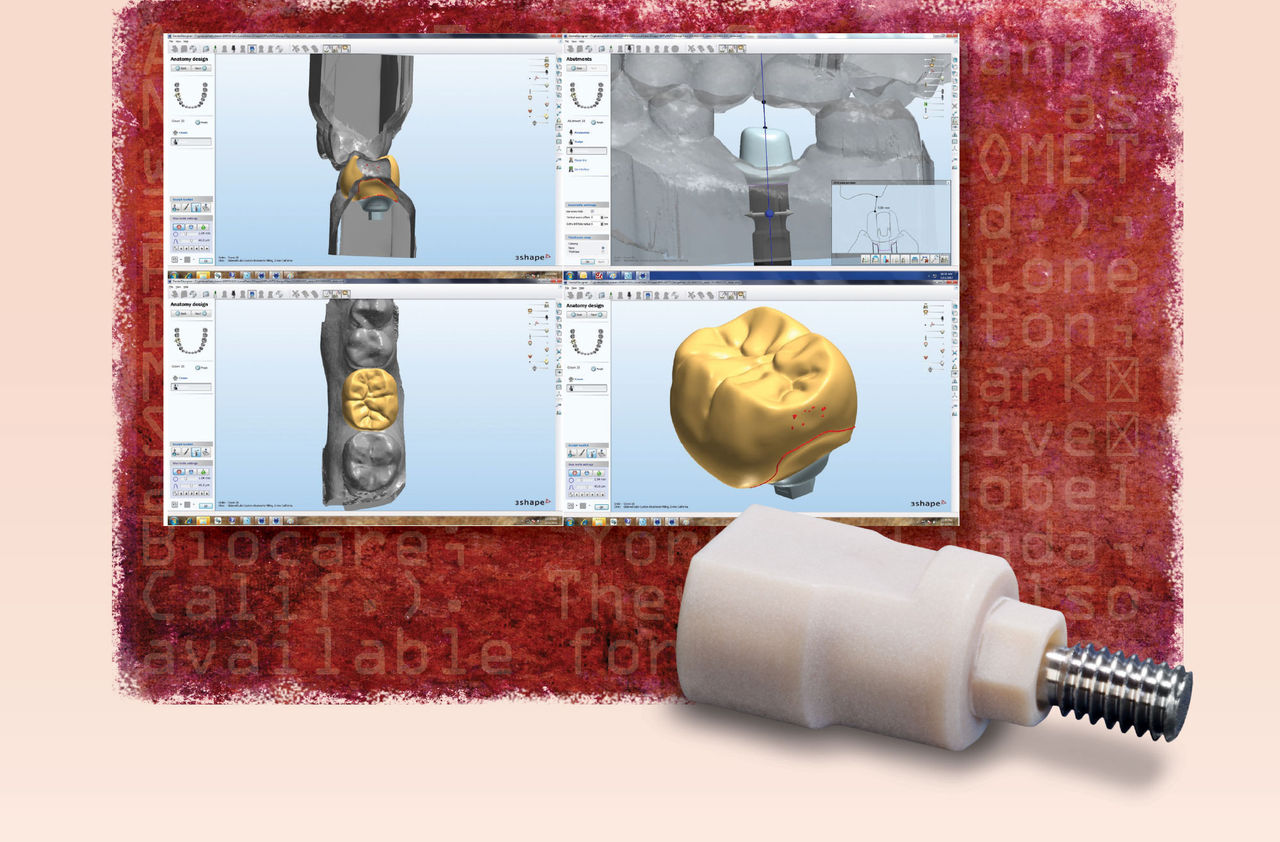
Next, we powdered the scanning abutment and adjacent teeth, and took the scans for the digital impression (Fig. 4). I then took the buccal bite and correlated (stitched) the models (Fig. 5), before replacing the scanning abutment with the healing abutment.


Our last step was to select Glidewell Laboratories as the dental laboratory in the CEREC Connect software, and complete the detailed prescription for the simultaneous fabrication of the CAD/CAM custom abutment and crown (Fig. 6). I selected a titanium abutment and BruxZir® Solid Zirconia crown. Before the lab began the milling process, the technician called as I had requested, and we fine-tuned the design (Fig. 7).


The case arrived at my office nicely packaged and organized. I tried in and verified the fit of the CAD/CAM abutment (Figs. 8, 9), torqued it to the recommended specifications, and then cemented the BruxZir crown with very minimal adjustment (Fig. 10).


Conclusion
As I have done many times, I could have handled this case in-office with good results using soft tissue models, a prefabricated titanium abutment prepared extraorally and an IPS e.max® crown (Ivoclar Vivadent; Amherst, N.Y.), but why would I want to spend more time doing laboratory work when I have the option of being more productive and delivering state-of-the-art dentistry to my patients? When you compare the simple steps involved in capturing digital implant impressions using scannable abutments to conventional impression systems, the digital method is simpler, easier and makes you a better, happier and more productive dentist.8
Dr. Carlos Boudet is in private practice in West Palm Beach, Florida. Contact him at boudetdds.com or 561-968-6022.
References
In April 2012, Sirona renamed its digital impression portal Sirona Connect. According to the company, the Sirona Connect portal, accessible via sironaconnect.net, is compatible with all existing versions of CEREC Connect.
- ^Zweig A. Improving impressions: go digital! Dent Today. 2009 Nov;28(11):100, 102, 104.
- ^Patel N. Integrating three-dimensional digital technologies for comprehensive implant dentistry. J Am Dent Assoc. 2010 Jun;141 Suppl 2:20S-24S.
- ^Mörmann WH. The evolution of the CEREC system. J Am Dent Assoc. 2006 Sep;137 Suppl:7S-13S.
- ^Boudet CA. CEREC Connect: a welcomed upgrade for CEREC users. Chairside. Spring 2011;V6I2:38-44.
- ^Fuster-Torres MA, et al. CAD/CAM dental systems in implant dentistry: update. Med Oral Patol Oral Cir Bucal. 2009 Mar 1;14(3):E141-5.
- ^Garg AK. Cadent iTero’s digital system for dental impressions: the end of trays and putty? Dent Implantol Update. 2008 Jan;19(1):1-4.
- ^Personal communication between laboratory owner and author.
- ^Lee SJ, Gallucci GO. Digital vs. conventional implant impressions: efficiency outcomes. Clin Oral Implants Res. 2012 Feb 22. Article first published online.