Fixing a Flawed Path of Insertion for a BruxZir Bridge Case of the Week: Episode 58

August 28, 2013
 image
Michael DiTolla, DDS, FAGD

Our weekly web series “Chairside Live,” which highlights a case recently received at the lab in each episode, continues to be a great way for me to share useful clinical tips and discuss potential pitfalls with our dentist viewers. If you have yet to tune in, episodes can be viewed on-demand at chairsidelive.com, or on YouTube and iTunes.

In this issue’s featured Case of the Week from Episode 58, I look at a case prepared by a dentist for a posterior BruxZir® bridge (Glidewell Laboratories; Newport Beach, Calif.). Even though the preps look really good, the path of insertion for the bridge is not ideal; in fact, one of the preps will require modification if the bridge has any chance of seating properly. The good news is we have a novel way at the lab of helping dentists accomplish a case like this. Let’s take a look at the case.

You’d be surprised how often we send doctors reduction copings and, for whatever reason, the necessary reduction is not done. I’m not sure if this is due to a lack of understanding about how to use a reduction coping, or if dentists think it’s only a suggestion.
Figure 1

Figure 1: Walking through the All-Ceramic department the other day, I noticed this case sitting on a technician’s bench with some paperwork next to it. It’s a nice-looking case for a BruxZir bridge on the lower left. There’s nothing wrong with prescribing a BruxZir bridge for this case, but I might have opted for a PFM bridge instead because the metal framework makes it the strongest bridge we have. (In reality, the strongest bridge we have is a cast-gold bridge without any ceramic material on it, but unfortunately, the lab cost — and the cost to the patient — would be equivalent to the GDP of a small nation. Also, it would not be very esthetic and would weigh about four pounds!)

Figure 2

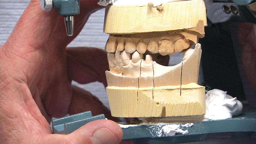
Figure 2: I notice the doctor provided us with enough occlusal clearance, and that there is some super-eruption of tooth #15. You may have heard me say that I haven’t done a single-unit PFM since about 2009 when we introduced our BruxZir material, and that, for the most part, I either do IPS e.max® (Ivoclar Vivadent; Amherst, N.Y.) restorations in the anterior or BruxZir restorations in the posterior. But when it comes to bridges like this one, I still think there is a use for porcelain fused to metal because even though BruxZir restorations are strong (view our “Hammer Test: BruxZir vs. PFM” video), they’re still an all-ceramic. With a span like we see in this case, there is a possibility that the BruxZir material can fracture. So while prescribing a BruxZir bridge for this case would be fine, if you’re wondering if there’s still a place in your professional life for PFMs, this would be it.

Figure 3

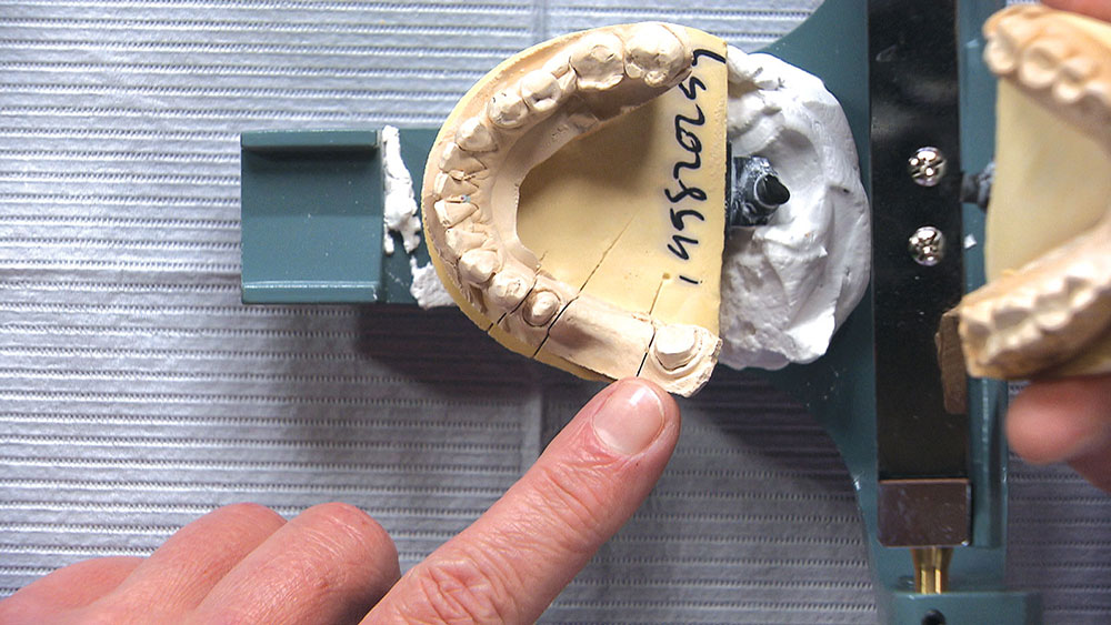
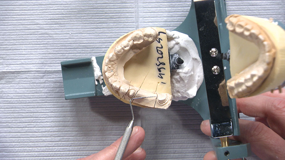
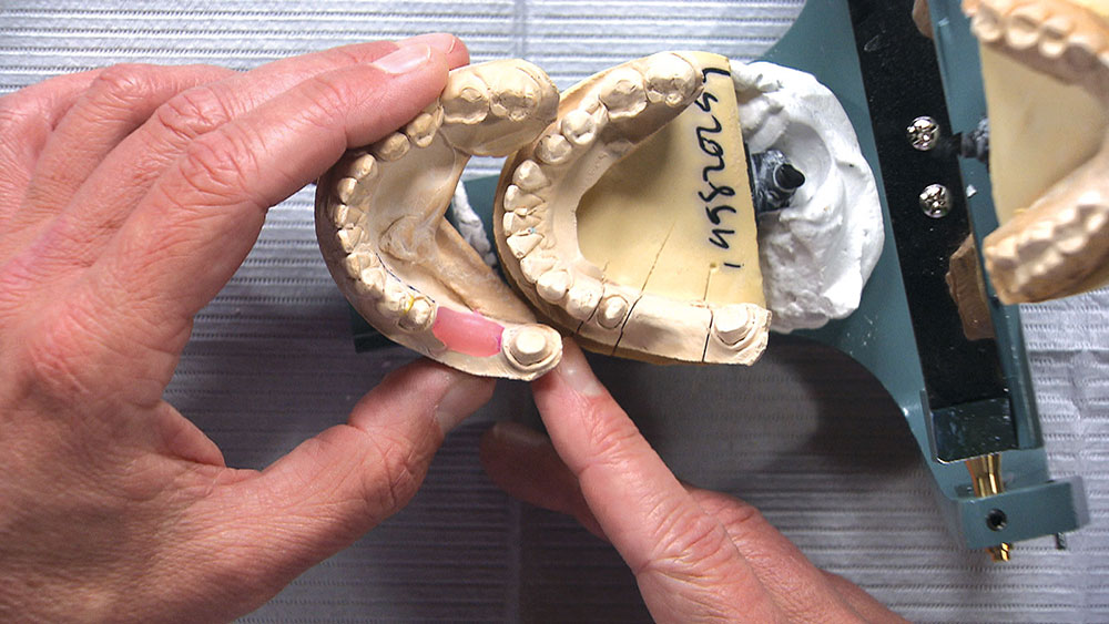
Figure 3: Looking at the stone model from the occlusal view, you’ll notice as we look down the path of insertion that there aren’t any visible undercuts on the bicuspid. However, we’re not able to see the mesial-lingual section on the molar.

Figure 4

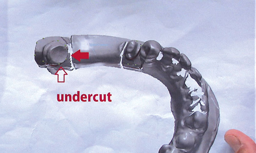
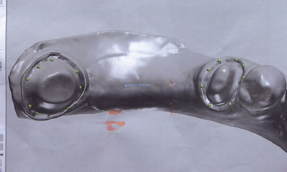
Figure 4: At the lab, we are able to scan a model like this and import it into our CAD software. One of the neat things about doing this is we don’t have to just eyeball it because the scan clearly shows there’s an undercut.

Figure 5

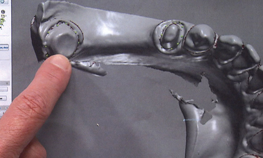
Figure 5: Scanning the model also allows us to measure where the undercut is. As you can see here, green dots are used to mark the margin all the way around the molar.

Figure 6

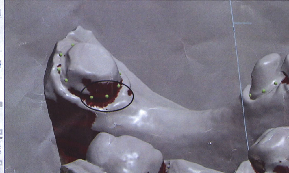
Figure 6: Then we can rotate the scan and the software marks exactly where the undercut is. Here, the circled portion identifies the undercut and the extent of it. How do we pass this information on to you, the dentist? Rather than having the patient come back in to re-prep the undercut area and take another impression, we would like to take the information from the scan and transfer it to you along with the bridge, so that you can make the necessary adjustments to get the bridge to fit without having to schedule the patient for an additional appointment. Some dentists aren’t comfortable doing this, and that’s fine. Sometimes we, as a lab, aren’t comfortable doing this either. You might have to specially request this and, frankly, if you aren’t able to do it this way, you might even have to pay for the remake.

Figure 7

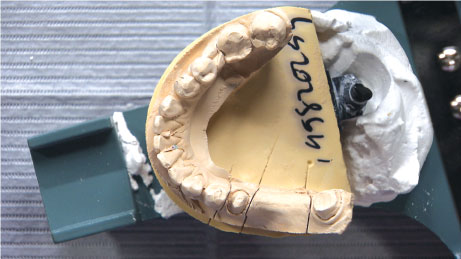
Figure 7: But what if we gave you a more predictable way to reshape the area and get rid of that undercut? We can do that today. In fact, as we look at the original stone model again, we can see where we’re not going to be able to draw because of the undercuts along the molar on the mesial-lingual. This was clearly identified in the scan in Figure 6.

Figure 8

Figure 8: One way to do this is to make a prep guide, which you can see here. This represents the same case, but now the undercuts have been removed. When we scan the prep guide, we will be able to see that we no longer have any of the undercuts that we had before.

Figure 9

Figure 9: With the scan of the prep guide, we can see the green dots marking the margins all the way around. We have eliminated all the undercuts we had in the first scan. So what does the dentist need to do? Looking back at Figure 8, he essentially needs to move from what he has in the original stone model to what we have in the prep model. He doesn’t have to touch the bicuspid at all; it’s just the mesial-lingual of the molar that needs to be prepped. How do we best communicate this information to the doctor?

Figure 10

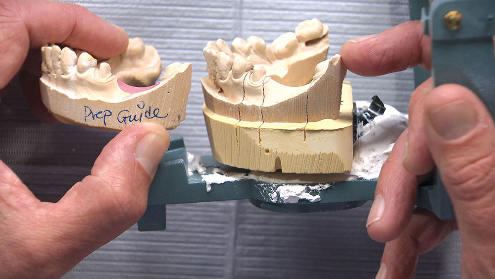
Figure 10: Looking at the original stone model in relation to the prep guide, you’ll notice we really haven’t reduced anything on the occlusal surface per se, but you’ll see a big difference between the slopes on the mesial part of the molars — how the prep is slanted back much more toward the distal. But that’s really the only area where we’ve lost any occlusal height. So now the question becomes, “What’s the best way to let the dentist know how much has to be reduced?”

Figure 11

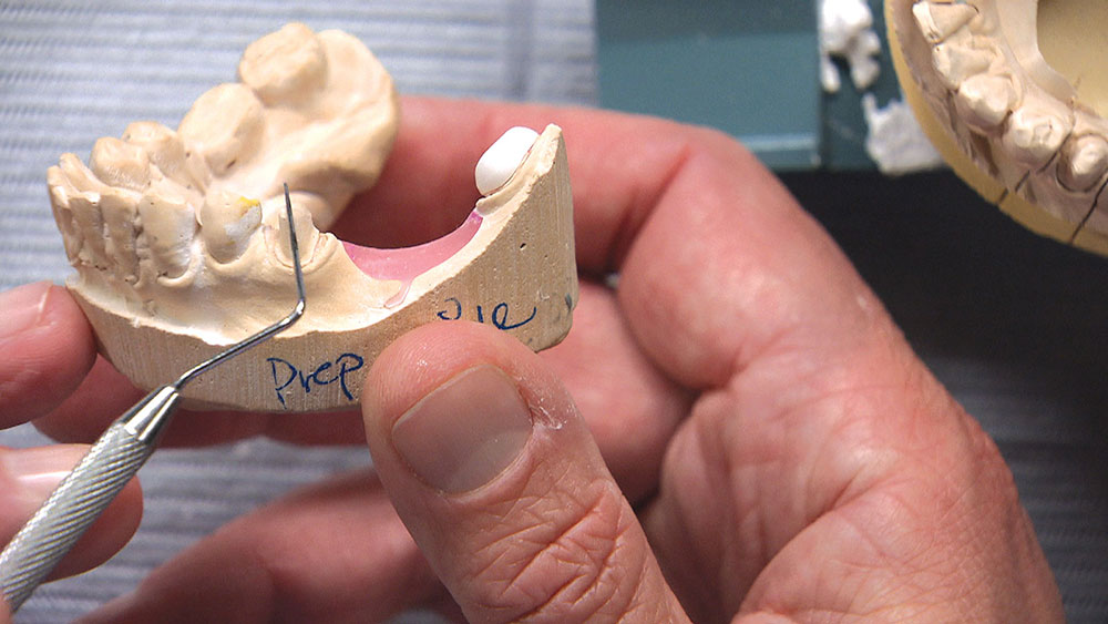
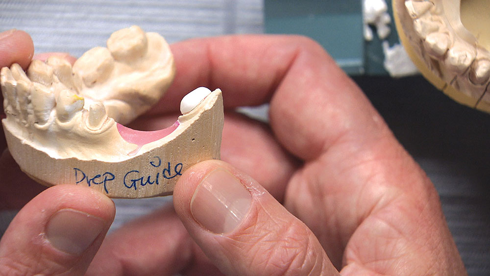
Figure 11: There are a couple things I typically have the lab do for me in a case like this. One is to make a reduction coping, like the zirconia one shown here on the molar. We typically use a reduction coping when a cusp tip is too long. For example, if we didn’t have enough clearance on the bicuspid that I’m pointing out with my explorer, and we needed some of the cusp tip removed, we would make a zirconia coping that fits around the tooth. It would have a hole in it where part of the tooth would be sticking out, and the doctor would be instructed to prep the tooth back until the preparation is flush with the zirconia coping. As simple and as useful as this seems, you’d be surprised how often we send doctors reduction copings and, for whatever reason, the necessary reduction is not done. I’m not sure if this is due to a lack of understanding about how to use a reduction coping, or if dentists think it’s only a suggestion.

Figure 12

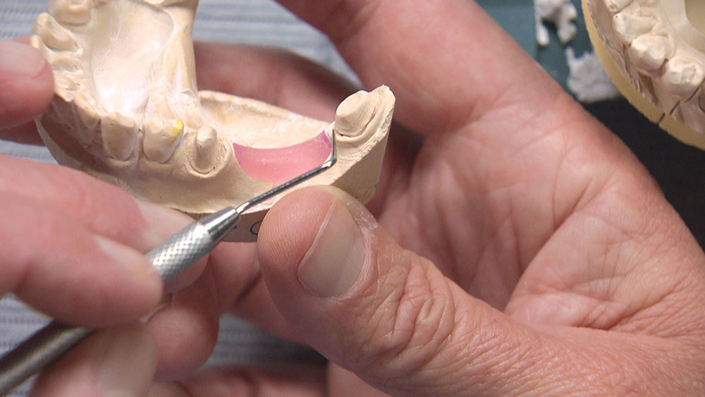
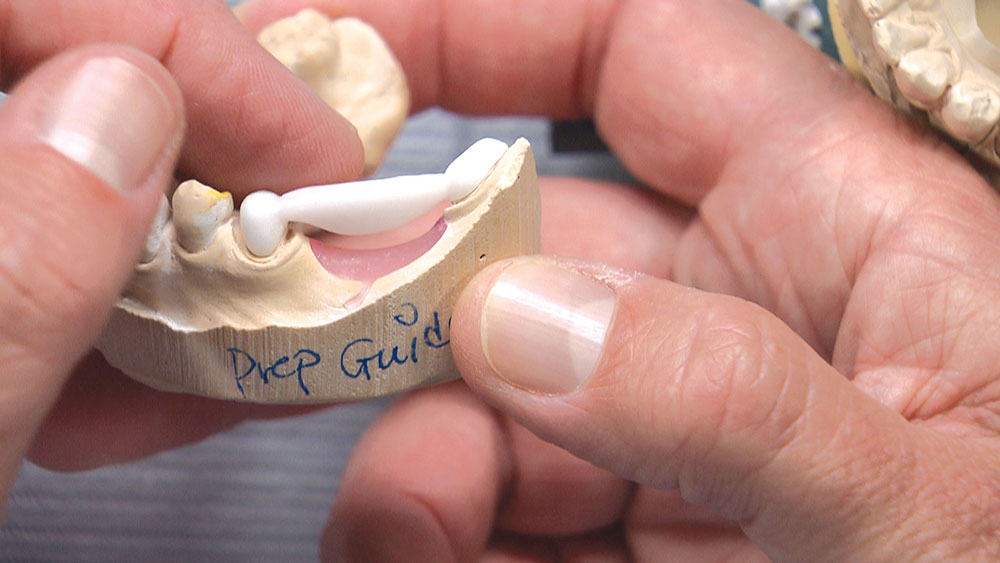
Figure 12: The zirconia coping is fitting down onto the molar on our prep guide. The problem is, unlike with a cusp tip where it sticks out of the top of the reduction coping to show you where the cusp needs to be prepared, this coping fits over the entire preparation. It will go down into place, and you can see on the margins that it will be closed, but it doesn’t give you that physical guidance of where to drill.

Figure 13

Figure 13: With a coping like this, the lab would identify the reduction area with a marker on the model. (NOTE: I have already prepped away the markings in this view.) Or, we would send you a copy of the scan showing the undercut on the mesial-lingual of the molar to show you where it needs to be adjusted.

Figure 14

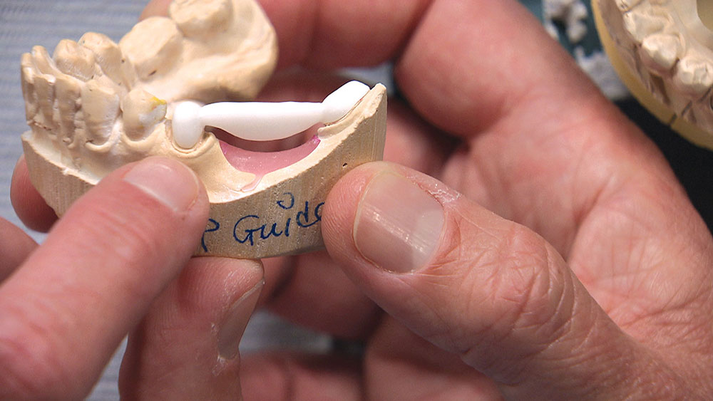
Figure 14: A single-unit coping can be difficult to work with, however, so I had the laboratory make me a multi-unit coping instead. Now we have a handle to grab onto while it’s on the prep guide. You’ll notice on the bicuspid that the coping stops short of the margin. Why is this? We want a clear, visible physical stop as we push the coping down into place on the bicuspid. Just in case the tissue is collapsed a little around the margin or there is some bleeding, we want the dentist to be able to know that it is seating all the way. You’ll know when you have reduced enough because you’ll be able to take the multi-unit coping in and out. Essentially, this coping replicates the zirconia framework that will be inside the bridge. We can do this for a PFM bridge as well.

Figure 15

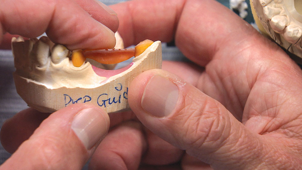
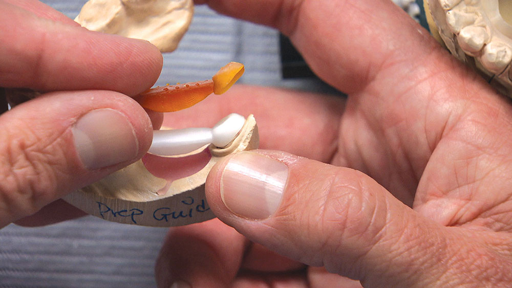
Figure 15: In some cases, the actual multi-unit coping you get from us may be printed on a 3D printer. We have many Perfactory® 3D printers (EnvisionTEC; Dearborn, Mich.) here at the lab, so this is often an easier, less expensive way for us to do this. It’s a little more difficult to see the printed coping in contrast with the yellow stone of the prep guide, so I had the lab mill a second one out of zirconia. In the mouth, however, the orange printed one might be easier to use, while on the teeth the white one might be a little more difficult to see.

Figure 16

Figure 16: No matter which version you receive from the lab, you will have a model showing you where to prepare. After preparing, it’s just a matter of trying in the reduction coping until it goes down all the way.

Figure 17

Figure 17: Now, if you were trying in the actual bridge, you can imagine that it might be more difficult to visualize because the margins may be slightly subgingival, which is why I prefer this method where the margins are trimmed a little short. This makes it easier to see whether you’ve reduced enough. With the multi-unit reduction coping, you can try it in and out on the model, and then take it right to the mouth to confirm that it’s seating the same way in the mouth as it is on the model. Using the bridge itself would also give you a feeling for that as you pushed it down, but dropping in the reduction coping to check how it’s seating and then reducing a little more makes this process easier. When you get close, you can drop in the actual bridge to check that the contact is good and that the occlusion is good when the patient bites together.

Figure 18

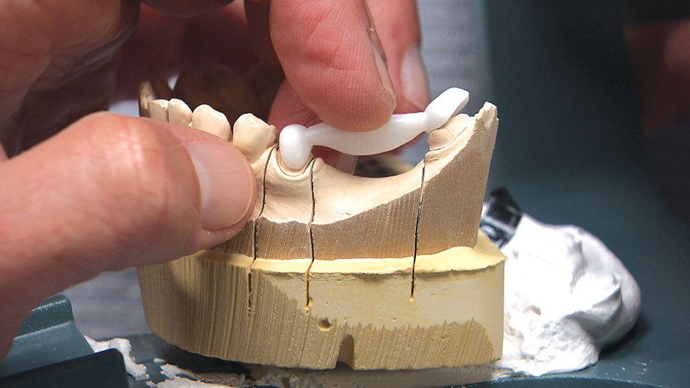
Figure 18: As you might expect, if we take the same prep guide zirconia framework and try it on the original stone model, it’s going to fit on the bicuspid very well because the bicuspid had no modifications, but it’s not going to fit onto the molar. Looking back at the prep guide in relation to the original stone model in Figure 10, you can see that the mesial wall of the molar had to be tapered back at an angle, which is where we lost a little bit of the height. This gives you an idea of how much tooth structure had to be removed for the framework to seat all the way and the permanent bridge to have a chance of seating properly.

Conclusion

As the dentist, you have a few choices in a case like this. You could have the patient come back in for another appointment to reshape the molar so the bridge will fit; or, rather than reshaping the back tooth, you could propose placing two implants between the bicuspid and the molar and then two single-unit crowns — though getting the patient to agree to this might be a stretch. Alternately, you could have the lab make you the actual bridge and a prep guide at the same time. Then, before trying in the permanent bridge, you could adjust the mesial and mesial-lingual portions of the molar until the framework goes down in the mouth like it did on the prep guide. If there are no contact issues or occlusion problems, you know the bridge is all the way down and you have saved yourself and your patient a return appointment. For this third approach to be successful, however, you will need to anesthetize the patient and be committed to doing the necessary preparation to get the bridge seated all the way and in one piece — especially if you’re doing a zirconia bridge without any kind of attachment, stress-breaker or telescopic coping. Whether you want to schedule a separate appointment or try to seat the bridge using the prep guide, the lab is more than happy to guide you in achieving clinical success.