In this issue:
Repair, Don’t Replace – Part 2: The ‘Saddle Crown’
Author
In the first part of this series on repairing an existing bridge (“Repair, Don’t Replace – Part 1”), a case was presented where a patient fractured the facial ceramic of a maxillary central incisor on a 6-unit porcelain fused to metal bridge. The facial fracture was stress related and did not involve the exposure of the underlying metal substructure. A successful repair was made by creating a veneer preparation into the ceramic and placing a new porcelain veneer on top of the affected surface.
Now, what happens if the ceramic fracture is substantially larger and involves the exposure of the underlying metal framework? The following case will demonstrate how, in some circumstances, the remaining porcelain can be removed from the metal and a “saddle crown” can be fabricated and cemented over the existing bridge.
A patient presented with a porcelain fracture on an anterior multiple-unit fixed bridge (Fig. 1). The fracture involved the entire facial surface of tooth #7 and exposed the metal framework at the disto-incisal angle. When viewed from the lingual aspect (Fig. 2), the fracture extends down to the porcelain-metal junction of the mostly metallic lingual surface. Because of the occlusal forces placed on this tooth in both protrusive and lateral excursions, it was decided to prepare the remaining porcelain down to the metal understructure and create a “saddle crown” to repair the defect.


The saddle crown consists of a facial and lingual surface only. These surfaces are only joined proximally incisal to the solder joint of the existing bridge. The preparation is designed to create negative space for this “telescopic” structure without compromising the structural integrity of the bridgework below.
A round-ended, tapered, coarse diamond is used to prepare the remaining porcelain and metal. Care must be taken not to score the adjacent proximal ceramic surfaces during the preparation phase (Figs. 3, 4). Also, be careful not to create undercuts when preparing the cervical areas of the preparation. In this case, it was a challenge to create sufficient space on the lingual surface without prepping away some of the existing metal framework. This should be kept to an absolute minimum to avoid compromising the strength of the existing bridge.


Figure 5 shows the incisal clearance created for the saddle crown as the patient closes into centric occlusion. This clearance is checked in protrusive and lateral excursions as well, to make sure adequate space has been provided. The preparation is polished with a round-ended 30 micron finishing diamond, followed by rubber polishing abrasives to smooth the cut metal substructure and porcelain.


Next, a retraction cord (Ultrapak® [Ultradent; South Jordan, Utah]) is placed on the facial and lingual marginal areas of the preparation (Figs. 6, 7). A two-cord technique is used, first placing a #00 cord, then a #1 on top of it. After a few minutes, the top cord is removed, leaving the #00 in the sulcus (Fig. 8). The master impression is then made using a syringeable light-bodied and heavy-bodied vinyl polysiloxane impression material (Honigum [DMG America; Englewood, N.J.]) (Fig. 9).


A provisional restoration is then fabricated using a bis-acrylic provisional material (Luxatemp® [DMG America]) and is cemented with polycarboxylate cement (Fig. 10). Digital photographs are provided to the ceramist to aid in characterization.


Figure 11 is a facial view of the saddle crown on the laboratory cast model. An incisal view of the master cast shows the preparation design that basically strips the porcelain down to the metal substructure on the facial and lingual, and is “tied in” with a continuous mesial and distal proximal finish line on the metal connectors of the preexisting bridge (Fig. 12). A proximal view of the completed restoration highlights the “saddle” design (Fig. 13). Interproximal margins are in metal and are located incisal to the metal connectors of the understructure. The lingual surface of the restoration is made in metal to match the preexisting bridge and limit the amount of lingual reduction (Fig. 14).


The completed saddle crown is tried in after removal of the provisional restoration (Fig. 15). After verification of fit and checking occlusion with articulating paper, the restoration is ready for cementation. In this case, resin-modified glass ionomer cement was used (Fig. 16). A 4-META-type cement is also good to cement metal to metal if retention is less than ideal. The cement is mixed according to the manufacturer’s instructions (Fig. 17) and pushed into place on the preparation (Fig. 18). It is recommended to hold the restoration in place until the cement is completely set, as hydraulic pressure can in some cases push the restoration incisally as the cement sets.


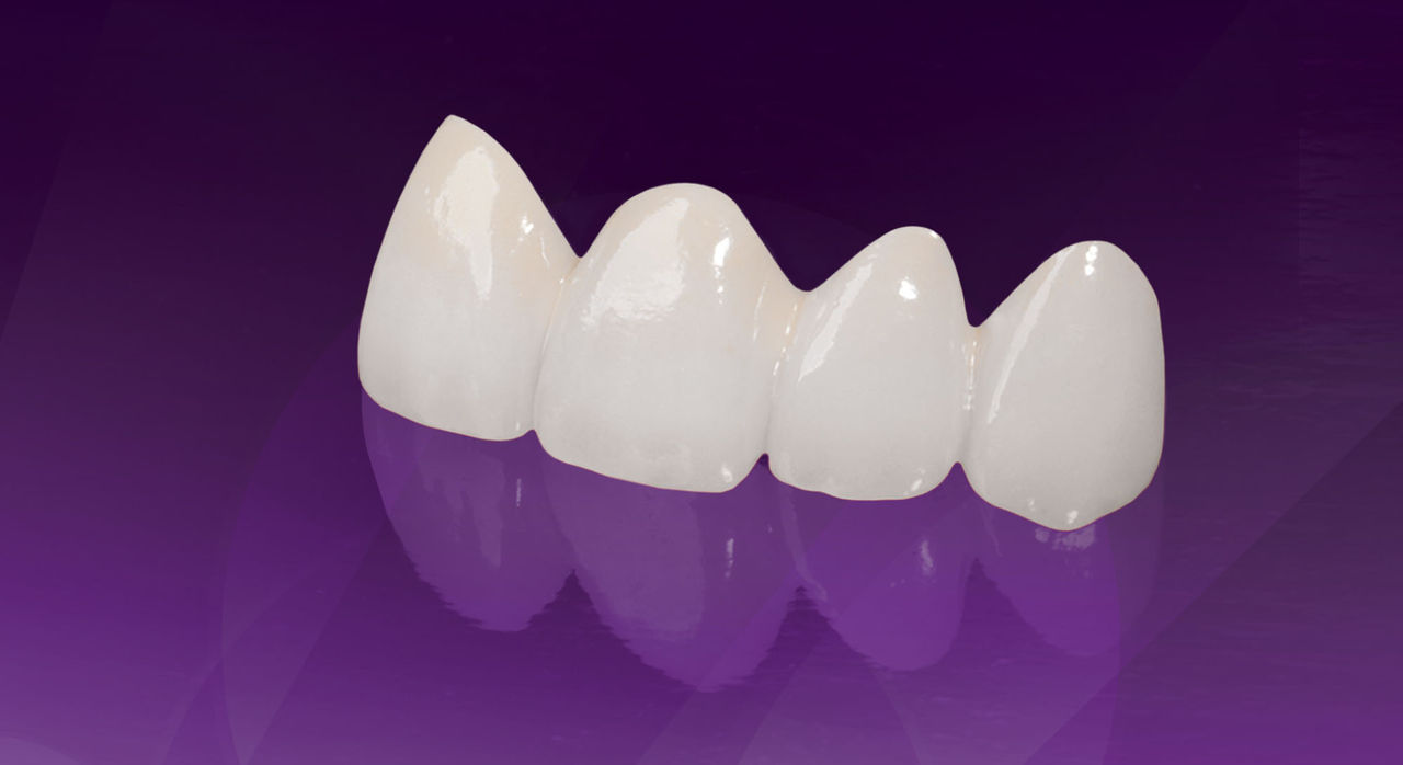
Figure 19 is a lingual view of the cemented restoration. The metal lingual surface of the saddle crown fits the adjacent metal margin of the bridge like an inlay. Figure 20 is a facial view of the completed saddle crown. Compare this to Figure 21, which is a facial view of the previous bridge prior to the fracture.


The esthetics of a repair made using a saddle crown makes it an excellent alternative to replacing the entire multi-unit restoration.
The esthetics of a repair made using a saddle crown makes it an excellent alternative to replacing the entire multiunit restoration. This solution works well in anterior and posterior regions for pontics as well as abutments.
Dr. Robert Lowe is in private practice in Charlotte, North Carolina. He lectures internationally and publishes on esthetic and restorative dentistry. Contact him at 704-364-4711 or boblowedds@aol.com.