An Insider’s Look at Veneer Preparation at Glidewell Laboratories

May 2, 2006
 image
Michael DiTolla, DDS, FAGD
An Insider’s Look at Veneer Preparation at Glidewell Laboratories

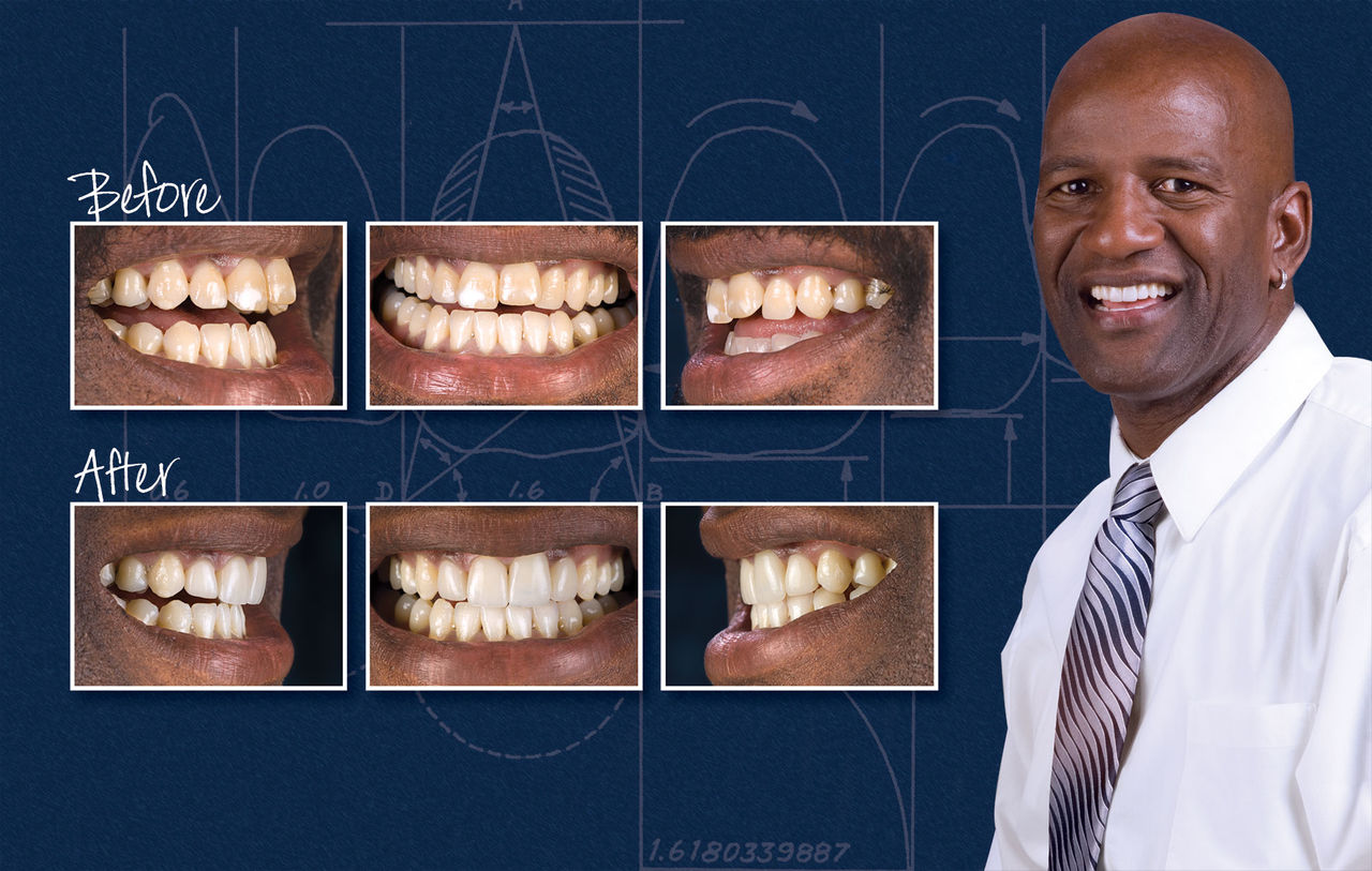
Almost every dental journal regularly runs clinical articles featuring porcelain veneers, and most of them seem to focus on showing before-and-after photographs. My experience in the laboratory is that many times the veneer cases we see don’t look as good as they could because there was not enough reduction done in the right areas. In this photo essay, I want to demonstrate how I use precontouring and depth cuts to assure that I give my dental technician enough reduction to work his magic. I also wanted to show the details of my temporary technique, as it greatly simplifies the process of making thin temporaries like these. I still believe that veneers are the most esthetic restoration in dentistry, and by following these precontouring and depth cut steps, I hope you find that you and your patients are more satisfied with your esthetic dentistry.

Figure 1

Figure 1: This 43-year-old male presented with multiple complaints about his smile. He has white spots on teeth #7–8. Tooth #9 is shorter than #8 and is tipped out to the facial. Tooth #10 is positioned too far to the lingual. Because of these alignment issues in the faciolingual plane, and the white spots on the teeth, he is not a candidate for no-prep veneers.

Figure 2

Figure 2: When the study model is viewed from the occlusal, the alignment problems become more apparent. Tooth #7 is rotated clockwise, causing the distal half of the facial surface to be too visible. Tooth #8 is rotated similarly to tooth #7. Tooth #9 is positioned too far facially and tooth #10 is positioned too far to the lingual. Again, because of the facial position of tooth #9, this patient is not a candidate for no-prep veneers.

Figure 3

Figure 3: Many times I will place an orthodontic arch wire on the study model to help visualize the alignment issues. This in turn allows me to preplan the tooth preparation in my head. For example, any tooth structure that is facial to the orthodontic arch wire will be removed through precontouring before any depth cuts are placed.

Figure 4

Figure 4: Here is a facial view of the diagnostic wax-up. As always, the lab has used white wax on a white stone model, which patients find very appealing when we use the wax-up to give them an idea of what their veneers will look like. The wax-up will also be used to fabricate the temporary veneers for this patient.

Figure 5

Figure 5: Because we are going to use the diagnostic wax-up for the temporaries, we need to clean it up a little. Using a sharp carving instrument, I remove any excess wax along the gingival margin, carving down to the sulcus on the stone model. The cleaner the diagnostic wax-up is in the gingival third, the easier the temporaries will be to fabricate intraorally because the temporary material will stop right at the gingival margin.

Figure 6

Figure 6: You may have noticed the difference in clinical crown length in teeth #8–9. As you can see here, #8 is 10.5 mm long. This is widely considered to be the accepted length for the average maxillary central incisor. For most patients, except for the very short and very tall, 10.5 mm makes for a very esthetic central incisor.

Figure 7

Figure 7: Tooth #9 is 12.2 mm long. Because the focus of esthetic dentistry often hinges on the central incisors, it is important that they are both visually pleasing and match each other as well. On this patient, the two centrals are different lengths, and our first thought is how to fix this. Do we remove tissue from tooth #8 so that it matches #9? Do we graft tissue back onto the cervical of #9 to make it match #8? Fortunately, when we refer to Figure 1, we can see that the patient’s smile line does not show the gingival margins, making it a non-issue that requires no correction.

Figure 8

Figure 8: To make a template from the diagnostic wax-up that can be used for temporary fabrication, we need to start with impression putty. This happens to be Capture® from Glidewell Direct. After ensuring that there is no latex powder on my hands, the putty base and catalyst are mixed according to the manufacturer’s instructions.

Figure 9

Figure 9: Once the putty is fully mixed, it is rolled into a hot-dog shape and pressed down over the diagnostic wax-up. Make sure the putty covers all of the teeth, not just those that have been waxed up. By pushing the putty on the teeth that will not be prepared, this acts as a seating index when you take the putty matrix into the mouth.

Figure 10

Figure 10: Let the putty set for 4 to 5 minutes on the diagnostic wax-up model. Keep in mind that it takes longer for the putty to set out of the mouth than in the mouth due to the cooler temperatures. As you can see here, the shape of the matrix isn’t important at this stage.

Figure 11

Figure 11: After the putty has set completely, gently remove it from the model. Using a sharp knife such as a Bard Parker #15, remove the excess putty material down to within 1 mm of the gingival margin. Do this trimming on the lingual as well as the facial.

Figure 12

Figure 12: Reline the putty matrix with a light or ultra-light viscosity syringe material. Place this wash material along the entire length of the matrix, making sure that it covers all of the teeth.

Figure 13

Figure 13: Seat the putty matrix with a light-body material inside back onto the diagnostic wax-up. You should see light-body material squirt out from around all the margins. Be sure to wait at least 5–7 minutes to remove this from the model because of the temperature differential from the model to the mouth. After trimming the excess wash material from around the margins, the putty/wash matrix is now ready to be used.

Figure 14

Figure 14: Prior to any tooth preparation, and more importantly prior to any tooth dehydration, the shade needs to be taken. Here, we are using the VITA Easyshade® (Vident; Brea, Calif.) to check the shade of the teeth to be prepared and the adjacent teeth as well. This information as well as a digital photograph of the teeth preoperatively will be sent to the laboratory, along with a stump shade photograph and a photograph of the temporaries in the patient’s mouth.

Figure 15

Figure 15: The occlusal view of the patient’s arch confirms the information seen on the study model. Thinking back to the orthodontic arch wire, I know I’m going to have to do some precontouring on the facial of tooth #9 and the distal half of tooth #8 prior to doing depth cuts if I have any hopes of getting them back into the proper arch form. The tooth structure that lies lingual to the orthodontic arch wire will not require any depth cuts facially.

Figure 16

Figure 16: I use an 856-025 bur for the precontouring. My goal is to remove enough facial tooth structure from tooth #9 and the distal half of tooth #8 to bring them in line with the orthodontic arch wire. Then I will place a facial depth cut the same depth as the thickness of the porcelain veneer to ensure this tooth stays within the orthodontic arch wire. In this picture the precontouring has been accomplished.

Figure 17

Figure 17: This is an MADC-006 bur from the Reverse Preparation Kit (Axis Dental; Coppell, Texas). This bur is a self-limiting 0.6 mm depth cut bur that is used on the facial surfaces of the teeth to be prepared after the precontouring is finished. I place four depth cuts on the facial surface of each tooth to ensure adequate and uniform reduction.

Figure 18

Figure 18: The depth cuts have now been placed in the facial surface of teeth #7–9. Again, notice no depth cuts have been placed in the facial surface on tooth #10 because it lies lingual to the orthodontic arch wire. I can’t stress how important it is to do the facial precontouring prior to these facial depth cuts. Many times it is the difference between esthetic success and failure.

Figure 19

Figure 19: The gingival depth cut and the gingival margin are accomplished simultaneously with the 801-021 bur from the Reverse Preparation Kit. This depth cut is performed at the gingival margin, being careful not to lacerate the gingiva with the bur. The depth cut is carried as far mesial and distal as possible. If the adjacent tooth is being prepared, this bur can be used to prepare the gingival margins of both teeth simultaneously.

Figure 20

Figure 20: The incisal edge depth cuts are placed with this MADC-015 bur. This self-limiting depth cut bur places an exact 1.5 mm depth cut in the incisal edge. Notice no incisal edge depth cut was placed in tooth #9 because it was already almost 1.5 mm shorter than tooth #8. Two depth cuts are placed in each incisal edge.

Figure 21

Figure 21: The 856-025 bur is used to blend the incisal edge depth cuts. This is done by holding the bur at a 90-degree angle to the long axis of the tooth. Once you can longer see any of the incisal edge depth cuts, it is time to place the lingual margin. This used to be more difficult and confusing than the method that I’m going to show you, but current veneer technique advocates a long bevel for the lingual margin. By tilting the handpiece 30–35 degrees to the lingual as seen here, I’m creating the long bevel and the mechanical resistance to keep the veneer from popping off during protrusive movements.

Figure 22

Figure 22: The 856-025 bur is used to blend all of the 0.6 mm facial depth cuts. This is where we also begin to blend the three planes of reduction: incisal, middle and gingival. We do not break contact between the teeth unless we need to shift the midline or if we have major tooth-size discrepancies.

Figure 23

Figure 23: This step is one of the most important, yet one of the more difficult ones to illustrate. Rotate the head of the handpiece so that the tip of the bur moves toward the lingual. We want to prepare the portion of the tooth gingival to the contact area without breaking the contact. This is called the elbow portion of the veneer preparation.

Figure 24

Figure 24: This drawing shows a saggital view of the elbow preparation. As you can see, the preparation wraps interproximally to the lingual while remaining between the contact area and the free margin of the gingiva. If you fail to prepare this area, the veneers might look good from the facial, but when the smile is seen from the side, the unprepared tooth structure will be visible.

Figure 25

Figure 25: After the elbow preparation has been made, a #00 cord is placed around the prepared teeth. Because we have not broken contacts, this retraction cord cannot usually be flossed into place. The cord is gently placed interproximally with a cord placement instrument, carried around the facial surface, cut with scissors and the loose end gently packed into the interproximal area.

Figure 26

Figure 26: The four #00 cords have been placed on the facial of teeth #7–10. The entire portion of the cord should be invisible at this point. As you can see, the gingival tissues have been retracted approximately 0.5 mm from where the original margin was placed. This allows us to clearly visualize the margins and drop them the last 0.5 mm so that we will have slightly subgingival margins.

Figure 27

Figure 27: In areas where you have a prepared tooth adjacent to an unprepared tooth, the 856-016 bur is a better choice for prepping the interproximal area and the elbow preparation. This smaller chamfer bur makes it easier for you to prep interproximal areas without damaging adjacent teeth.

Figure 28

Figure 28: Many of us were taught that a rough finish on a preparation is desirable for micromechanical retention. While this may be true for standard crown and bridge cements, the bond achieved through resin cementation exceeds this. Therefore, it becomes desirable to polish the preparations, especially in the area of the gingival margins. A fine grit 850-018-KR bur is my favorite bur for removing all the rough edges from my preparations.

Figure 29

Figure 29: You need to be careful for sharp angles on your preparations. The most common place for these to occur is on the mesial and distal corners of the incisal edge. Here, I am using a 3M ESPE Sof-Lex™ disc (St. Paul, Minn.) to round off the corners of the incisal edge.

Figure 30

Figure 30: The Sof-Lex disc can also be used on the facial surface to blend the three planes of reduction. It is especially important to make sure that the incisal third of the preparation curves back toward the lingual. This will help keep your veneers from looking like buckteeth. In this picture I am using the Sof-Lex disc to achieve this reduction of the incisal third of the preparation.

Figure 31

Figure 31: Once the preparation is finished, we now place the 2E cord around the prepared teeth. Because we have not broken contact between the teeth, we typically will use one piece of retraction cord for all of the prepared teeth.

Figure 32

Figure 32: The top cord in the two-cord technique (2E cord) will stay in place 8–10 minutes and then will be removed prior to taking the impression. The bottom cord (00) will stay in place during the impression to ensure that there is no bleeding around the preparations.

Figure 33

Figure 33: A closer look at the finished impression shows that the margins of all the prepared teeth are clearly visible. Almost as important, excess impression material beyond the margin is also visible. This impression of the root structure apical to the margin provides the technician with important emergence profile and margin location information.

Figure 34

Figure 34: For porcelain veneers that are 0.6 mm thick such as these, it is important to take the stump shade into consideration. Using Ivoclar Vivadent’s stump shade guide, St9 appears to be the closest match. This photograph will be forwarded to the lab technician in order to help them better achieve the final desired shade, through the use of shaded resin dies that the veneers will be placed on.

Figure 35

Figure 35: You will be amazed how simple this temporary technique is going to be. Pick a shade of bis-acryl temporary material one shade lighter than you think is the proper shade. In this case I should have chosen two shades lighter. Inject the bis-acryl material into the putty/wash matrix in the areas of the prepared teeth.

Figure 36

Figure 36: Place the putty/wash matrix with the bis-acryl inside into the patient’s mouth. To make sure that the matrix is seated all the way, put your fingers on the matrix on the areas of the unprepared teeth and push down hard to assure the matrix is seated all the way. Sometimes it takes this extra push to ensure that the matrix is completely seated.

Figure 37

Figure 37: When you place the matrix, you should see excess bis-acryl material above the matrix, as seen in this picture. Leave the matrix in place for 2–3 minutes. Usually we would remove the matrix earlier than this, but when fabricating temporary veneers, we want to mechanically lock them into place. Therefore, the only mistake we can make in this technique is trying to remove the matrix too early rather than too late.

Figure 38

Figure 38: After removing the putty/wash matrix, this is what you will see. Because we trimmed the diagnostic wax-up in the area of the gingival margin, you can see how clean these temporaries are at the gingival margin. We simply need to remove the excess material, which I am doing here with a cord-packing instrument. If there is excess material in the gingival embrasure, use a thin carbide-finishing bur to remove it.

Figure 39

Figure 39: Here is a shot of the temporaries while the patient smiles. The fabrication of the temporaries took less than 10 minutes. For patients who are having 8–10 veneers done and are thinking about choosing high-value veneers, we use bleach shade bis-acryl for the temporaries. In cases like this one, in which only four teeth are prepared, we have to make them blend with the adjacent teeth.

Figure 40

Figure 40: This retracted view gives a better look at the temporary restorations. Because they were made from an impression of the diagnostic wax-up, the alignment issues have been corrected. Even though the clinical crowns of teeth #8–9 are different lengths, as you saw in Figure 36, the patient’s smile line does not reveal this discrepancy.

Figure 41

Figure 41: This photo shows an occlusal view of the temporaries. You can see that, as a result of the precontouring and the use of the diagnostic wax-up for our putty/wash matrix, we have achieved our ideal arch form. An alginate impression will be taken of the temporaries and forwarded to the lab technician so they can see how the information on the diagnostic wax-up blends into the patient’s dentition.

Figure 42

Figure 42: This is a facial view of the patient’s temporaries after two weeks. While the shade I chose had too low of a value, the temps have otherwise served the patient well. On this patient, I relearned a lesson that I already knew: Always choose one shade lighter than you think is the correct shade for temporary veneers.

Figure 43

Figure 43: Because the temporary veneers are mechanically locked into place, it is almost always easier to cut them off rather than try to remove them with hemostats. Using a 57 bur, we slice through the facial and incisal aspects of the temporary. To make it easier to see what I am doing, I leave the water off during these cuts. The goal is to section most of the way through the temporary without touching the bur to the tooth.

Figure 44

Figure 44: Once the cuts have been placed in the temporary material, a right-angle crown remover is used to crack the temporaries. Typically, we will make these facial and incisal cuts on every other tooth because when you pop off one veneer, the one next to it comes off as well.

Figure 45

Figure 45: You need to be very careful to remove excess temporary material from the gingival embrasures. When you lock the temporaries into place, material always fills these embrasures. In fact, I believe that these undercuts are why we can mechanically lock these temporaries into place. I am using a piece of Oral-B® Glide floss (Procter & Gamble; Cincinnati, Ohio) with a knot tied in it to remove the excess material from the gingival embrasures.

Figure 46

Figure 46: Using my Orascoptic HiRes™ loupes (Middleton, Wis.), I inspect the preparations to make sure there is no excess temporary material left in or around the teeth. Drying the teeth will also make any excess temporary material more visible.

Figure 47

Figure 47: Initially, the veneers are tried in to the mouth individually to check for marginal fit without the influence of potential tight contacts. Once we have verified all of the veneers fit individually, they are tried in collectively to evaluate contacts.

Figure 48

Figure 48: The veneers are now tried in with try-in paste, in this case Ivoclar Vivadent’s Appeal® (now known as Variolink® Veneer) (Amherst, N.Y.). I always start with the translucent shade of the try-in cement, which in this system is known as the Medium Value, or 0, shade. I find the more translucent the cement, the more natural the restoration looks.

Figure 49

Figure 49: When I tried the veneers in, I noticed that I could still see some white spots on teeth #8 and #9 showing through the veneers. You can see these spots more clearly in the picture of the preps in Figure 43. Rather than use a more opaque cement under the veneers, I decided to mask the white spots.

Figure 50

Figure 50: The white spots that were so apparent on the before pictures (Fig. 16) diminished as we prepared the teeth; however, they were still somewhat present when the preparations were finished. Using a #1 round carbide under magnification, I began to prepare into the white spots in order to place some composite over them. With minimal preparation, white spots were removed.

Figure 51

Figure 51: I decided to place a small amount of composite into each of the white spot preparations, making sure not to place enough composite to alter the fit of the veneers. I begin by etching the preparations for 10 seconds and then rinsing.

Figure 52

Figure 52: OptiBond® Solo™ (Kerr Corporation; Orange, Calif.) solo is then placed into the preparation, thinned with a dry microbrush, and oil-free air is used to evaporate the solvent. The bonding agent is then light-cured for 10 seconds.

Figure 53

Figure 53: Point 4 composite (shade A2) was used to fill the preparations. Notice the difference in how the preparations look in this figure when compared to Figure 34. It will now be possible to use the translucent veneer cement.

Figure 54

Figure 54: The lab has already etched the internal aspects of the veneers with hydrofluoric acid. After rinsing out the water-soluble try-in cement and drying the internal aspect of the veneer to verify the etch, we use a microbrush to place the silane on the internal aspects of the veneer. It is left in place for 60 seconds, then air-evaporated.

Figure 55

Figure 55: We use a unidose pumice (Pumice Preppies™ [Whip Mix Corp.; Louisville, Ky.]) to ensure that all of the temporary material, try-in cement and saliva has been removed from the tooth prior to veneer cementation.

Figure 56

Figure 56: The teeth are etched with 37% phosphoric acid for 10 seconds on dentin and 15 seconds on any remaining enamel. Care is taken not to leave the etch in contact with gingival tissues, as this can cause bleeding if the tissues have been irritated by the temporaries. If the tissues are irritated, I will often place a #00 retraction cord prior to seating the veneers.

Figure 57

Figure 57: The veneers on teeth #8–9 are always placed first, and always placed simultaneously. It is critical that the veneers on these two teeth are placed correctly and match each other. I will often push gently with an orangewood stick from the incisal and the facial at the same time to ensure the veneer is completely seated.

Figure 58

Figure 58: The veneers are held gently in place from the incisal with an orangewood stick while my dental assistant cures for 2–3 seconds using the “tack-and-wave” technique. I check the cement with an explorer to see if it is in its gel state. If not, my assistant will cure it for another 1–2 seconds. Once it is in the gel state, I use an explorer to clean up as much excess as possible, and dental floss to clean interproximally.

Figure 59

Figure 59: A safe-sided serrated strip such as this one from Axis Dental is invaluable for opening contacts that have been inadvertently bonded closed. If we ever ran out of these strips, I would have to reschedule the patient’s seat appointment; that’s how important these strips are to properly seating a veneer case.

Figure 60

Figure 60: Once all four of the veneers have been placed and cleaned up with an explorer and floss, it is time to remove the excess veneer cement from the lingual margin and adjust the occlusion. My favorite bur for this is a 7408 12-fluted carbide. The shape of this bur helps it to work particularly well on lingual surfaces.

Figure 61

Figure 61: It can be difficult to identify and remove cured veneer cement (especially translucent) from the facial surface of the veneers without damaging the porcelain. I avoid burs at all cost while doing this. Here, I am using a OneGloss® disc from Shofu (Menlo Park, Calif.), a composite polishing disc, to remove the resin cement from the veneer without causing any damage to the veneer whatsoever.

Figure 62

Figure 62: Here is a retracted facial view of the veneers immediately after cementation and cleanup. Because of the health of the patient’s gingiva, it was not necessary to place a retraction cord prior to cementing the veneers.

Figure 63

Figure 63: This is an occlusal view of the veneers. Notice how the facial alignment has been improved as compared to Figure 15. The precontouring of the teeth prior to placement of the depth cuts makes this possible.


A Smile Preview: Diagnostic Wax-Ups

I have always considered diagnostic wax-ups a critical part of the porcelain veneer process. A big reason I always use diagnostic wax-ups is to give the patient an accurate idea of what their finished case could look like. In fact, I have always been suspicious of digital imaging programs because of the way they show patients what their smile could look like. Many of these systems have a smile library in which a smile is somewhat arbitrarily taken from the library and “pasted” over the patient’s existing smile. Unfortunately, this method of imaging doesn’t take the patient’s tooth position or hard or soft tissue architecture into account, and can show the patient an “after” scenario that is literally impossible to achieve.

With the diagnostic wax-up the lab or dentist removes the desired amount of tooth structure from the pre-op model and the veneers are waxed onto the patient’s actual prepped teeth. This method accurately shows the patient, dentist and lab technician what is realistically available for this patient. In fact, one of my favorite things to do is to take a polyvinylsiloxane impression of a diagnostic wax-up, fill it with a bleach shade bis-acryl temporary material such as Temphase from Kerr, and place it over the patient’s unprepped teeth and let it set to give the patient an intraoral preview of what their new smile will look like. Obviously, it’s not a perfect fit because no teeth have been prepped, but it is a nice way to transfer the information from the diagnostic wax-up to the patient’s mouth.

The diagnostic wax-up also helps many patients make up their minds about treatment just by looking at the wax-up and comparing it to their existing smile. It is for this reason that I insist that all diagnostic wax-ups be fabricated from white stone models with white wax added for the veneers.

Yellow models and yellow wax just don’t elicit the same emotional response from patients when they view them, even though darker models and wax may make it easier for the dentist and technician to see certain details such as surface texture, etc. The bottom line is, if you are planning on showing the diagnostic wax-up to the patient or are going to let them take it home to show to their spouse, make sure your lab uses white models and white wax.

The diagnostic wax-up can also act as a financial screening tool. We charge $20 per tooth for this service, but we have the patient pay for it. So for a typical 8-veneer case the diagnostic wax-up would cost $160, and that amount is credited toward the overall case fee if the patient decides to have the treatment done. Years ago I would pay for the wax-up myself, only to find out that the patient wasn’t all that serious about having the treatment done.

After I became the owner of five or six wax-ups, the decision was made to have the patients pay for them. Any patient who balks at the $160 fee for the wax-up to see what their new smile could look like is probably not that serious about having the treatment done. This keeps you from wasting $160 on a wax-up you don’t need.