My First Implant

December 1, 2009
 image
Michael DiTolla, DDS, FAGD
My First Implant Hero Image

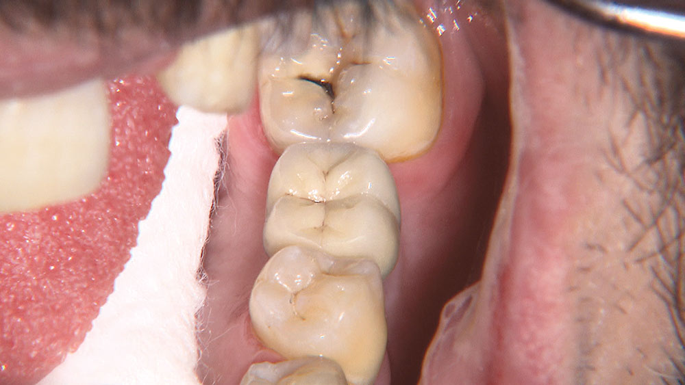
It’s not often that I praise patients for not following the advice of their dentist, but after placing my first implant that is exactly what I did. Ten years earlier, when this 32-year-old male patient had tooth #19 extracted, his dentist suggested they do a 3-unit bridge to replace the missing tooth. The patient didn’t like how much it was going to cost, but more importantly, he opposed the idea of prepping two adjacent teeth to replace one missing tooth, especially when he had no restorations on the lower arch. I told the patient he made a good decision not having the bridge done, since that is what allowed us to place the implant without harming either of his adjacent teeth. Fixed bridges seem to create as many periodontal problems as the restorative problems they were meant to resolve. Throw in the fact that the two abutment teeth could potentially need endodontic treatment now or later, and a compelling case is made for the single tooth implant.

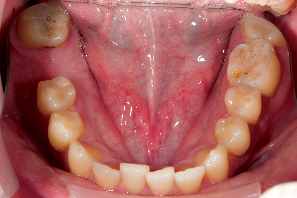
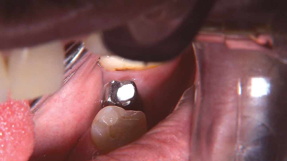
This 32-year-old male patient presented with a missing lower left first molar. I had been instructed to look for a patient like this for my first implant: young, healthy and with lots of bone. I liked the idea of getting my feet wet in the posterior, where esthetics would most likely not be an issue.

I’ve always known that patients would rather stay in my office than be referred to another office, but I was afraid to surgically place an implant. Up to this point I had been restoring implants for some time and had taken numerous implant courses. However, when our implant department convinced me that Digital Treatment Planning technology would eliminate the guesswork, I decided I was ready to give it a try.

Here are some step-by-step pictures of my first implant. I can honestly say it was the most fun I have had in a long time, and it was easier than almost any crown prep I’ve recently done. I wish there was this much technology available to walk me through molar endo, wisdom tooth extractions or multiple-unit bridge preps. Take advantage of this technology and utilize the Digital Treatment Planning expertise of Glidewell’s implant department. If your first experience is anything like mine, you will immediately start looking for your second implant case. Or, if you are a part of a surgical-restorative team, you will find that this service provides an easy way to integrate and utilize this technology with your implant cases.

Because we planned on placing a NobelReplace™ implant, this case was done utilizing the NobelGuide™ Guided Surgery System. This photo essay will walk you through the process.

Figure 1

Figure 1: This 32-year-old male patient presented with a missing lower left first molar. I had been instructed to look for a patient like this for my first implant: young, healthy and with lots of bone. I liked the idea of getting my feet wet in the posterior, where esthetics would most likely not be an issue.

Figure 2

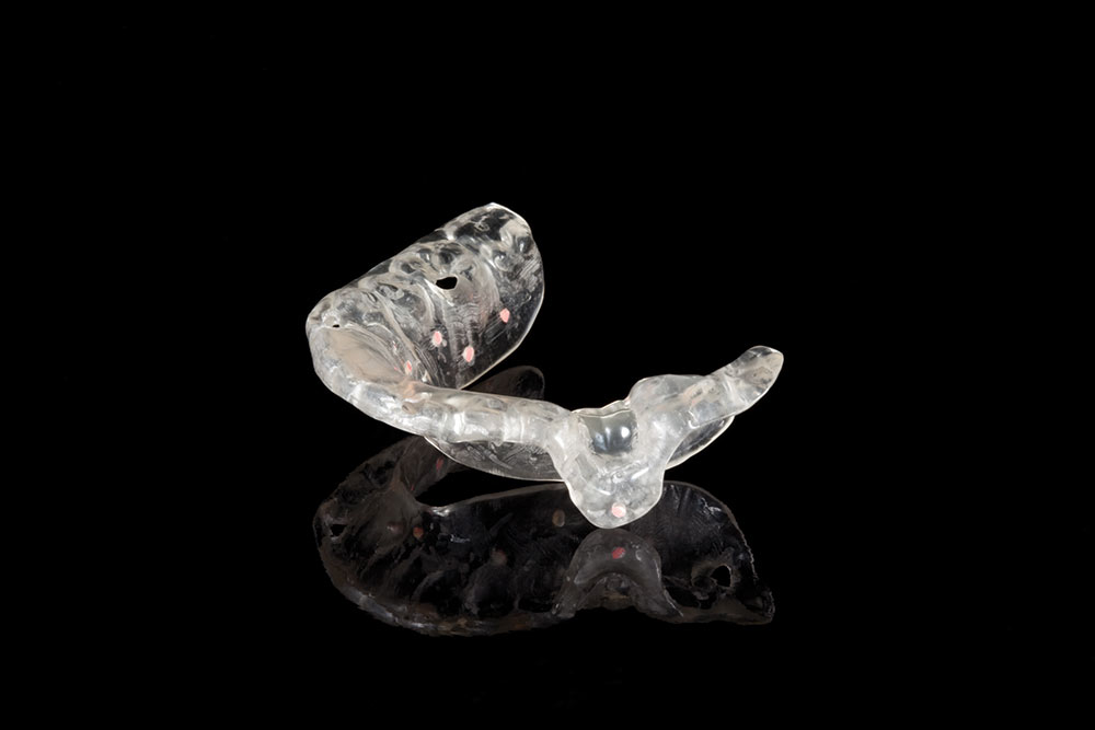
Figure 2: After sending study models to the implant department, a radiographic guide and radiographic index were fabricated for the patient to wear to their cone beam scan appointment. We had the patient stop by the office prior to this appointment to ensure the radiographic guide fit well, that he could place it, and that he could verify the guide was completely seated.

Figure 3

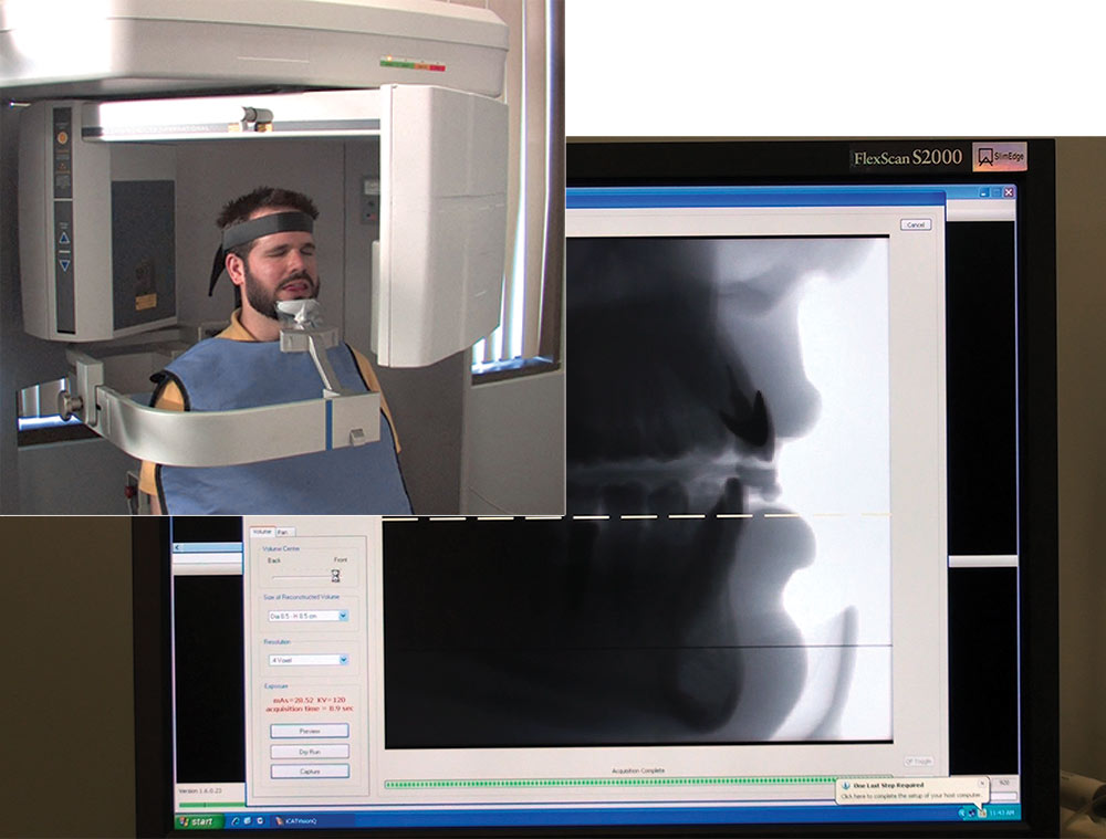
Figure 3: At the radiology lab, the patient places the radiographic guide and radiographic index and uses a mirror to verify that it is seated. It is important that the technician be familiar with the scanning protocol. NobelGuide requires a dual scan — one of the patient with the radiographic guide in place and one of the appliance alone. A benefit of having the cone beam scan unit in your office or building: one of your assistants is present to ensure the guide is properly placed.

Figure 4

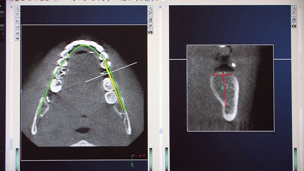
Figure 4: The software reconstructs the scan files into slices, as well as a three-dimensional rendering of the mandible that can be viewed from any angle. Cross-sectional slices, which follow the arch, allow you to view the mandible in the exact spot you plan on placing the implant.

Figure 5

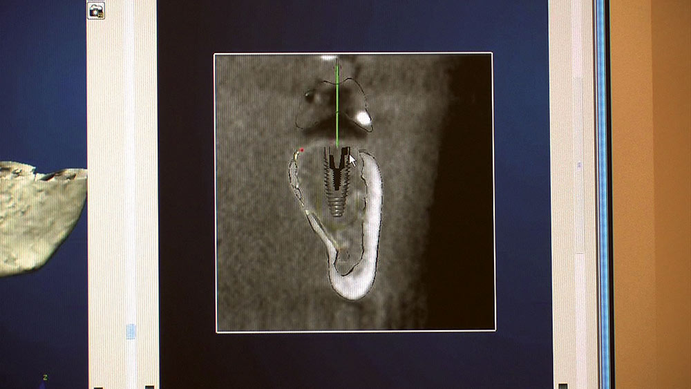
Figure 5: Digital Treatment Planning allows our implant department to place virtual implants into the ideal position from both surgical and prosthetic perspectives.

Figure 6

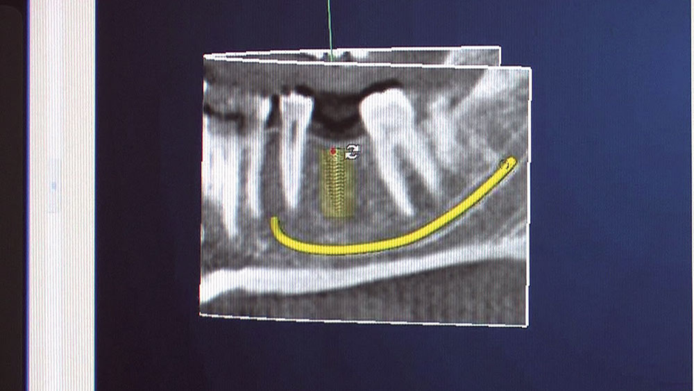
Figure 6: As important as the placement of the implant is the identification of the inferior alveolar canal. As you can see it was well below not only the implant, but also the yellow safety zone around the proposed implant. The risk of paresthesia was one of the concerns that had kept me from placing implants for the first 20 years of my career.

Figure 7

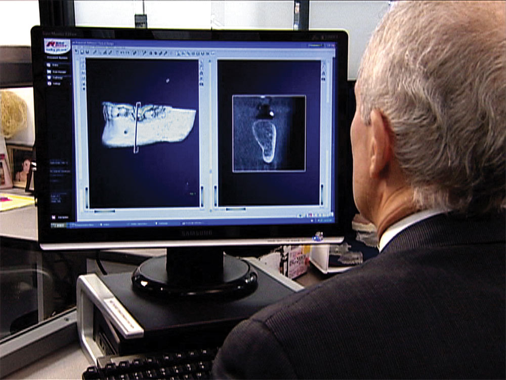
Figure 7: As part of the Digital Treatment Planning service, I had a WebEx conference with one of the lab’s experienced implant clinicians, Dr. Brad Bockhorst. Brad walked me through the case and answered my questions about the guided surgery procedure. At the end of the conference, I instructed Brad to fabricate the surgical template.

Figure 8

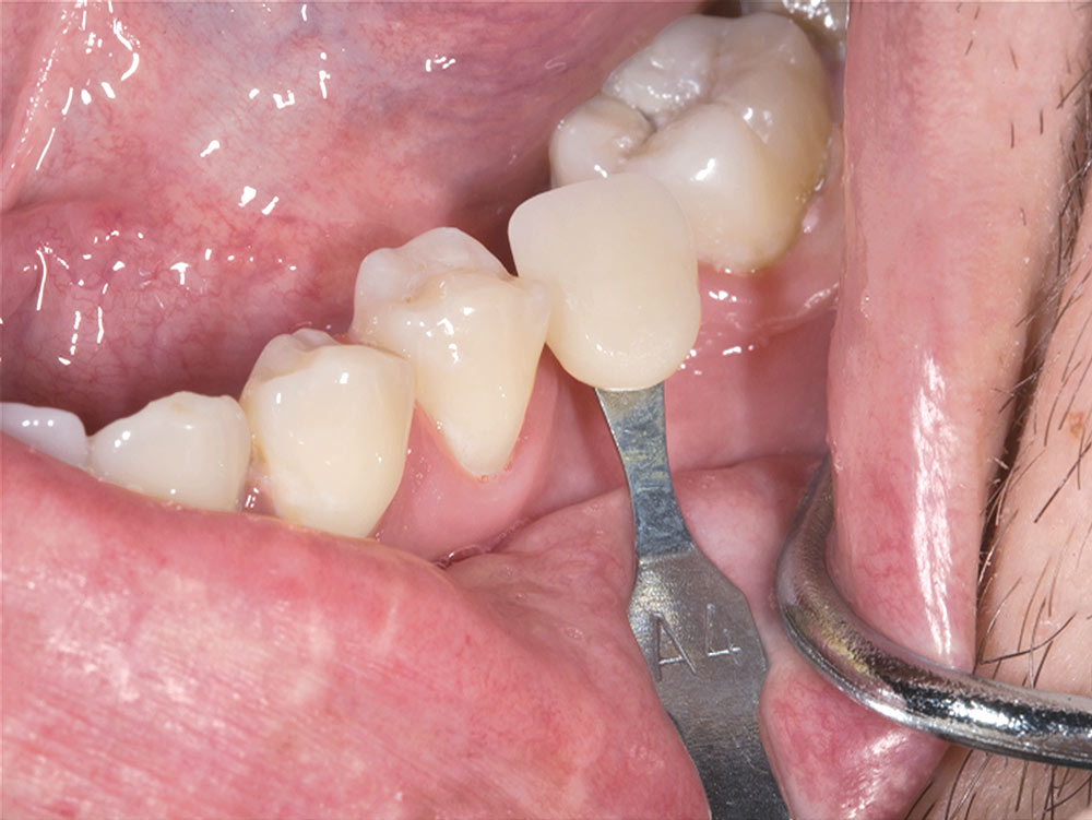
Figure 8: My VITA Easyshade® Compact told me the nearest shade was an A4, so I placed the A4 shade tab in the mouth and took a photograph to send with the case. Admittedly, this is far more important with anterior restorations, but I still find that lab technicians try harder when provided with a picture of the shade tab in place.

Figure 9

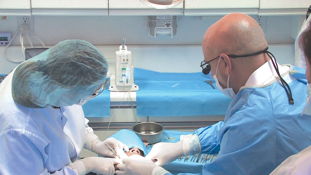
Figure 9: Because this surgical procedure is confined to the area where tooth #19 used to be, I administered local anesthesia (buccal and lingual infiltrations) with my STA™ System. Even though there is no PDL to utilize in this case, I now use the STA System exclusively because it greatly lowers my stress when giving injections. Notice my assistant is wearing a hair net. Notice I don’t need to.

Figure 10

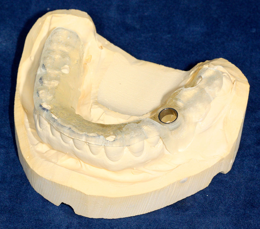
Figure 10: A close-up view of the surgical guide on the model. It should seat into place, much like an occlusal splint. The guide will have some inspection windows from which cusp tips will stick out so that you can verify that the guide is completely seated. The metal sleeve in the surgical template controls the angle and the depth of the implant drills.

Figure 11

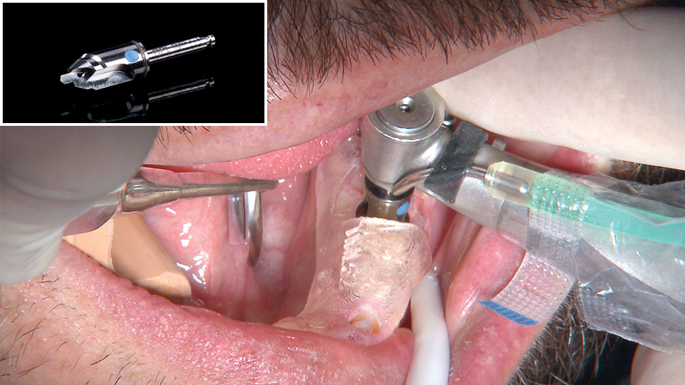
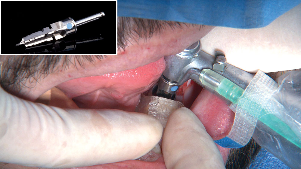
Figure 11: With the patient anesthetized, we begin the procedure by inserting the surgical guide and using the start drill. The tip of the start drill creates a countersink in the bone, while the upper part of the start drill acts as a tissue punch. Because no grafting was necessary, no flap was utilized as part of the procedure. Note how the large diameter of this drill fills the sleeve in the surgical template.

Figure 12

Figure 12: The 2.0 mm drill is the first one to be used to full depth, in this case 13.0 mm. Because the 2.0 mm drill is much narrower than the opening in the surgical template, a drill guide is placed in the sleeve to ensure there is no play in the system, and the correct angulation is maintained. A depth stop is placed on the drill to prevent over-insertion. For our first cut into bone, the handpiece is running at 2,000 rpm.

Figure 13

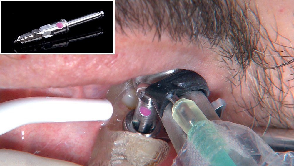
Figure 13: Now that the depth of the osteotomy has been established, it’s time to widen it with our tapered burs. The 8.0 mm Narrow Platform drill is a self-limiting drill that cannot go deeper than 8.0 mm. The drill widens the coronal section of the osteotomy to a depth of 8.0 mm, but because it is narrower than the final Wide Platform drill another drill guide is used in the surgical template to maintain an accurate angle.

Figure 14

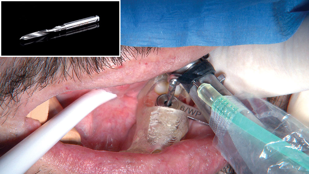
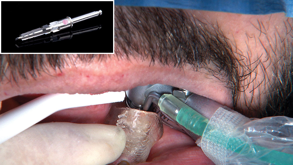
Figure 14: Now that the osteotomy has been widened in the upper two-thirds, it is time to take that down to the full length with the 13.0 mm Narrow Platform drill. As with all guided tapered drills, it has a built-in depth stop to ensure that you don’t go too deep. The surgical handpiece has internal irrigation being fed with a sterile water source to prevent heat buildup in the osteotomy site.

Figure 15

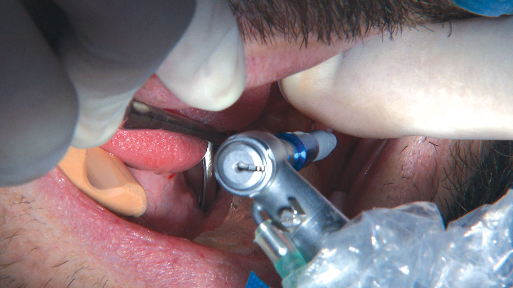
Figure 15: We are now using the 13.0 mm Regular Platform drill. Like most tapered drills, it only takes a few seconds to drill to depth. As with all tapered drills, the handpiece speed is 800 rpm to ensure the bone does not become overheated.

Figure 16

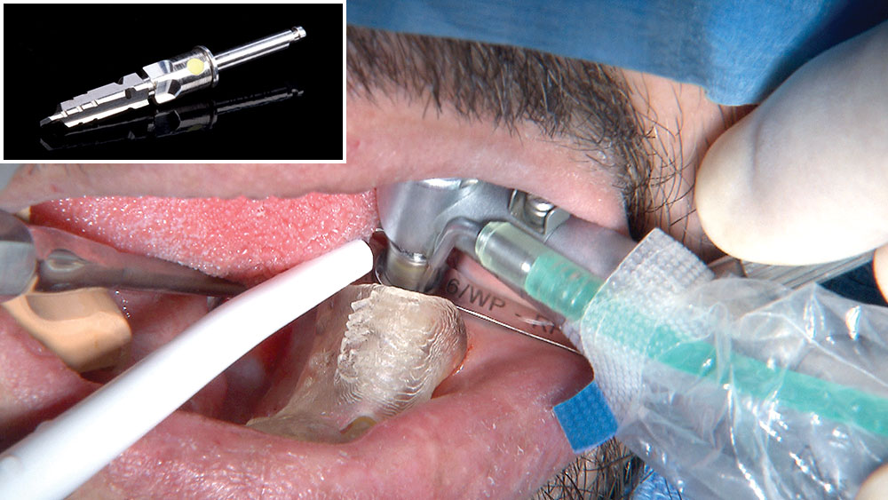
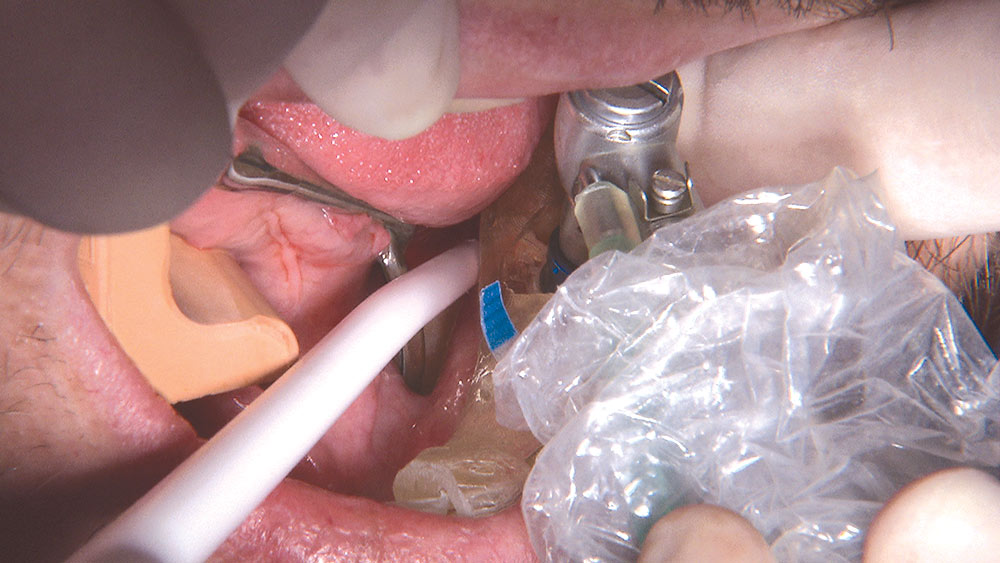
Figure 16: This is the tapered drill that will bring the osteotomy to its final size, the 13.0 mm Wide Platform drill. As you can see, the top part of the drill is the Wide Platform and is the same diameter as the start drill; therefore, no drill guide needs to be placed in the surgical template. A few quick vertical strokes establishes our final osteotomy size.

Figure 17

Figure 17: The 5.0 x 13.0 mm NobelReplace implant with the guided implant mount is now on the handpiece and is being carried into the mouth. Like all of the instruments used up to this point, it will be inserted through the sleeve in the surgical template and advanced apically until it is almost fully seated. The handpiece is now running at 25 rpm.

Figure 18

Figure 18: With the handpiece rotating so slowly, there is no hurry to get the implant down into place as it threads itself into the osteotomy. A millimeter or two before the implant reaches its final depth, I stop and remove the handpiece so I can hand seat the implant with a torque wrench.

Figure 19

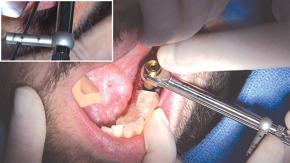
Figure 19: The torque wrench is used to fully seat the implant and to manually verify the 35 Ncm torque achieved during placement. The torque value gives you an indication of the implant’s primary stability. At this point, the implant mount and surgical template are removed and you can see whether or not the top of the implant is where it is supposed to be. It was!

Figure 20

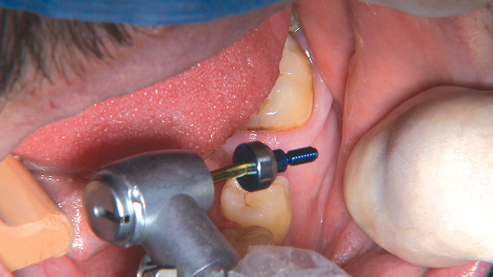
Figure 20: The healing abutment is placed with the handpiece, although it can also be placed by hand to a torque of 15 Ncm. From the start of the procedure it has been approximately 20 minutes, which is pretty impressive for my first implant. As you have seen, there hasn’t been a lot of skill required on my part thanks to Digital Treatment Planning and Guided Surgery technology.

Figure 21

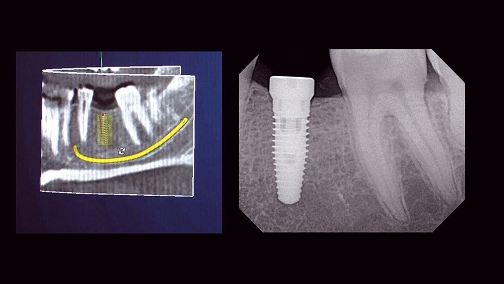
Figure 21: On the left is a picture from my WebEx conference with the Digital Treatment Planning Team. On the right is the periapical radiograph taken as soon as the healing abutment was seated. Looking at the position and the angulation of the proposed implant and the actual implant, I am confident I could not have achieved this result freehand.

Four Months Later

Figure 22

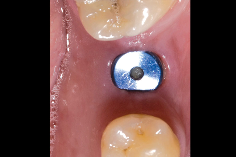
Figure 22: With the implant now osseointegrated, we are ready to seat the patient’s final restoration. Because we utilized Digital Treatment Planning and Guided Surgery, the abutment and crown were made without me ever having to take an impression. The master model was made utilizing the surgical template and the prosthesis fabricated while the implant was integrating. I use my diode laser to remove a small amount of tissue that had crept up over the mesial edge of the healing abutment.

Figure 23

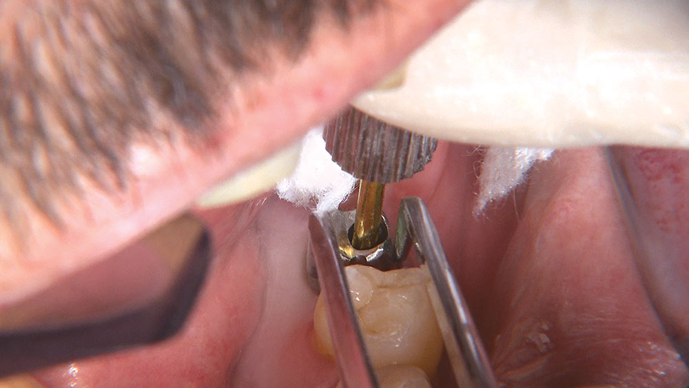
Figure 23: After removing the healing abutment, the Inclusive® Custom Titanium Abutment is held in place by my dental assistant as I tighten the abutment screw. The torque wrench is used to confirm full seating and that an adequate amount of force has been used (35 Ncm).

Figure 24

Figure 24: Once the abutment screw has been tightened sufficiently, we place a small cotton pellet over the head of the screw and then seal the opening with a little temporary filling material.

Figure 25

Figure 25: The crown was tried in, and margins, contacts and occlusion were checked. I was surprised that it fit as well as it did, considering that I had not taken an impression besides the alginate study models at the beginning of the case. The impressive technology offered through Glidewell’s Digital Treatment Planning Services made my first implant a piece of cake, both surgically and prosthetically.

For more information on Glidewell Laboratories Digital Treatment Planning services, call 800-497-3692.

NobelGuide and NobelReplace are trademarks of Nobel Biocare (Yorba Linda, Calif.). STA is a trademark of Milestone Scientific (Livingston, Calif.). Easyshade is a registered trademark of Vident (Brea, Calif.). Inclusive is a registered trademark of Glidewell Laboratories (Newport Beach, Calif.).