Photo Essay – Utilizing Digital Impressions and Chairside Mills

June 24, 2016
 image
Justin Chi, DDS, CDT
Photo Essay – Utilizing Digital Impressions and Chairside Mills

I’ve spoken with many dentists who have implemented intraoral scanners into their practices, and the overwhelming majority have said these devices have made them better dentists. Digital impressions provide instant feedback when a preparation is scanned, and allow users to evaluate their own work, ultimately improving their skills and the quality of care for the patient. When digital impressions are paired with chairside mills, there are several advantages for both the patient and the clinician. As we eliminate the need for a separate appointment for crown seating, we empower patients who have difficulty taking time from work or other obligations. No longer do clinicians have schedule interruptions dealing with lost or failed provisionals. With the opportunity to deliver an accurate final restoration in a single visit, long seating appointments and adjustments can be eliminated. The workflows available today through digital dentistry are better than they’ve ever been, resulting in fewer variables — and making for stress-free dentistry.

An advantage of CAD/CAM is that each clinician can choose his or her own personal preference when setting up contact values and parameters to enter into the software.
Figure 1a
Figure 1b

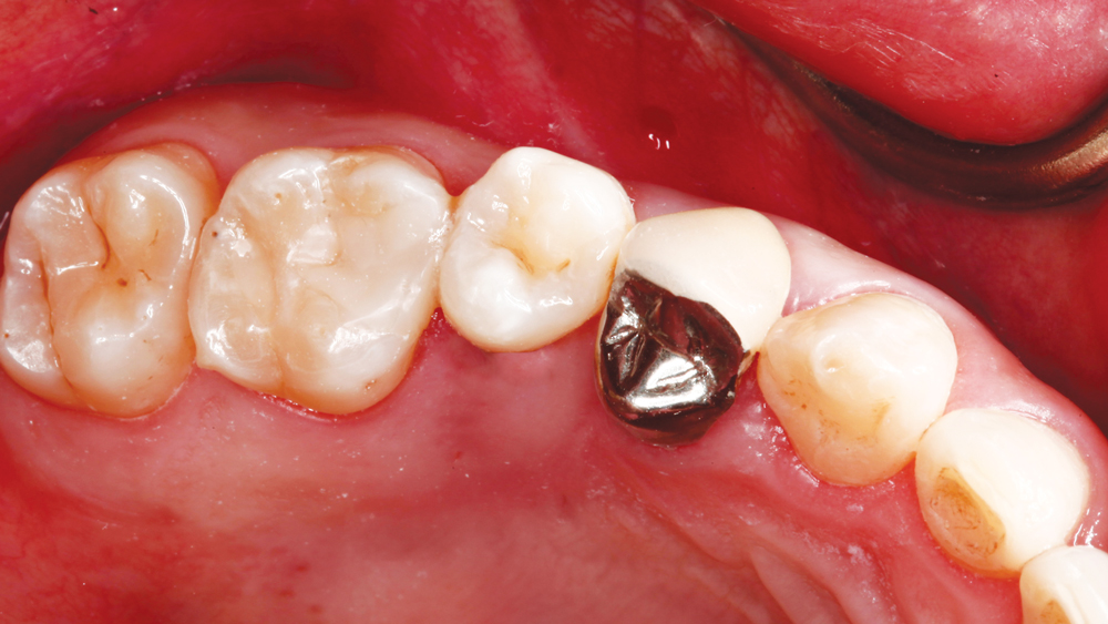
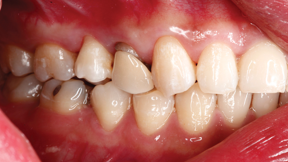
Figures 1a, 1b: A patient presented with a previously endodontically treated tooth #5 with an existing PFM over a metal post, with open margins and circumferential recurrent decay. I wanted to provide a better restoration for this patient, so I removed the PFM and evaluated the remaining tooth structure.

Figure 2

Figure 2: Due to minimal remaining coronal tooth structure, I positioned the margins slightly subgingival to establish a ferrule so I could place a fiber post (ParaPost® Taper Lux [Coltène/Whaledent Inc.; Cuyahoga Falls, Ohio]) for support and retention of the core buildup material.

Figure 3a
Figure 9b

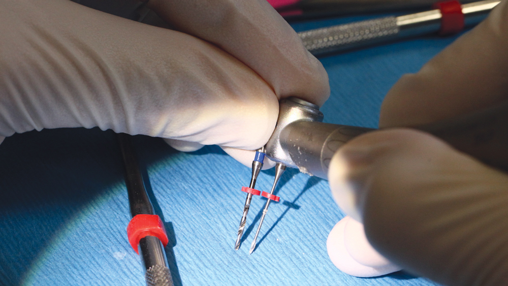
Figures 3a, 3b: I used a series of drills to create the space for the post so that it extends at least half the length of the bone-supported root structure to achieve maximum support.

Figure 4a
Figure 4b
Figure 4c

Figures 4a–4c: The fiber post was bonded into place using RelyX Unicem (3M ESPE; St. Paul, Minn.). After the post was in place, I created a buildup using Clearfil Photo Core (Kuraray America, Inc.; New York, N.Y.). I like Clearfil Photo Core because it molds like composite and has a feel similar to that of tooth structure during prep refinement. After the buildup was made, I prepared it to create the ideal dimensions for an all-ceramic restoration.

Figure 5

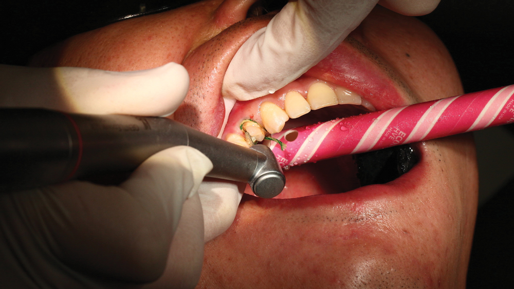
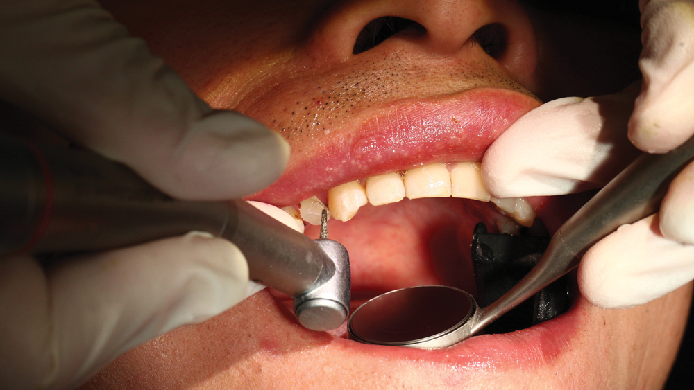
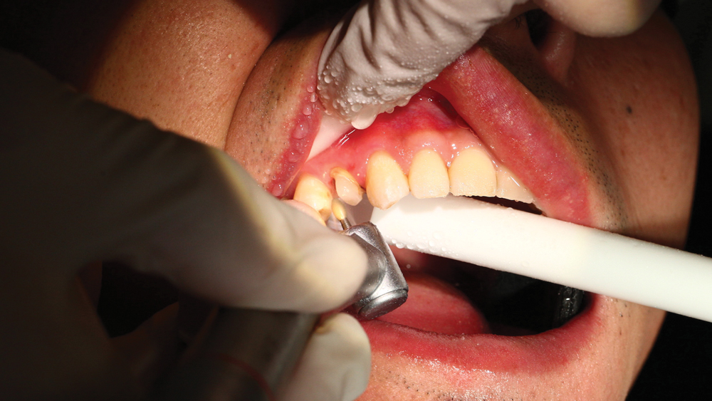
Figure 5: For Obsidian® lithium silicate ceramic crowns (Glidewell Laboratories; Newport Beach, Calif.) like the one I milled for this case, I like to reduce 1 mm axially and 1.5–2 mm occlusally. One of the most common issues with crown preps is the lack of sufficient reduction to enable the restorative material to provide strength and esthetics. For chairside restorations, I like using the same shape of bur in my handpiece that is used by the milling unit; in this case, a round-ended tapered diamond bur.

Figure 6

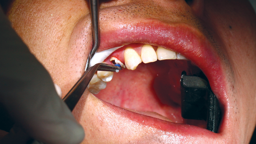
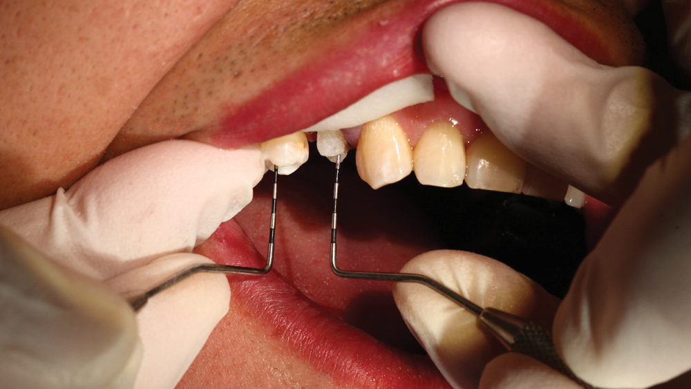
Figure 6: To verify that my occlusal reduction is adequate, I placed a probe in the deepest pit of tooth #4 and a probe in the middle of the prepped buildup to evaluate the relative height of the deepest anatomy on that adjacent tooth. This way, I know to reduce the prep 1.5 mm below the measurement on tooth #4 to allow for similar esthetic anatomy to be created in the restoration while still meeting the material thickness requirement.

Figure 7

Figure 7: After the prep was reduced properly, I made sure it displayed rounded internal angles due to the fact that the mill uses a round bur and cannot mill sharp intaglio angles without over-milling, and because sharp angles can create stresses on all-ceramic restorations.

Figure 8

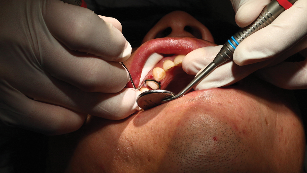
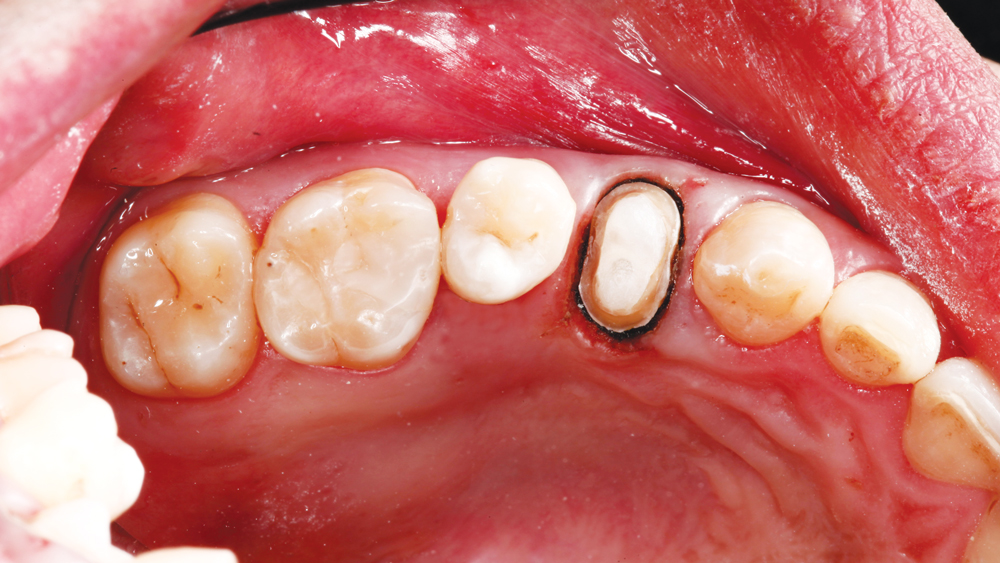
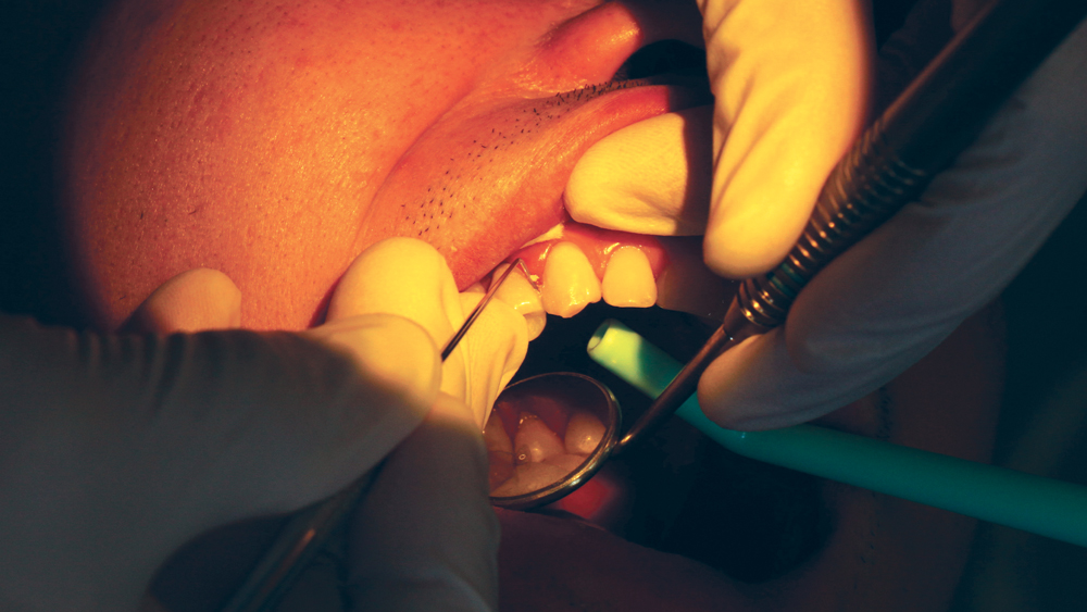
Figure 8: Once the prep was completed, I proceeded with the Two-Cord Impression Technique, which calls for a small cord (I used size 000) to be placed first to provide apical retraction and to help with moisture control.

Figure 9a
Figure 9b

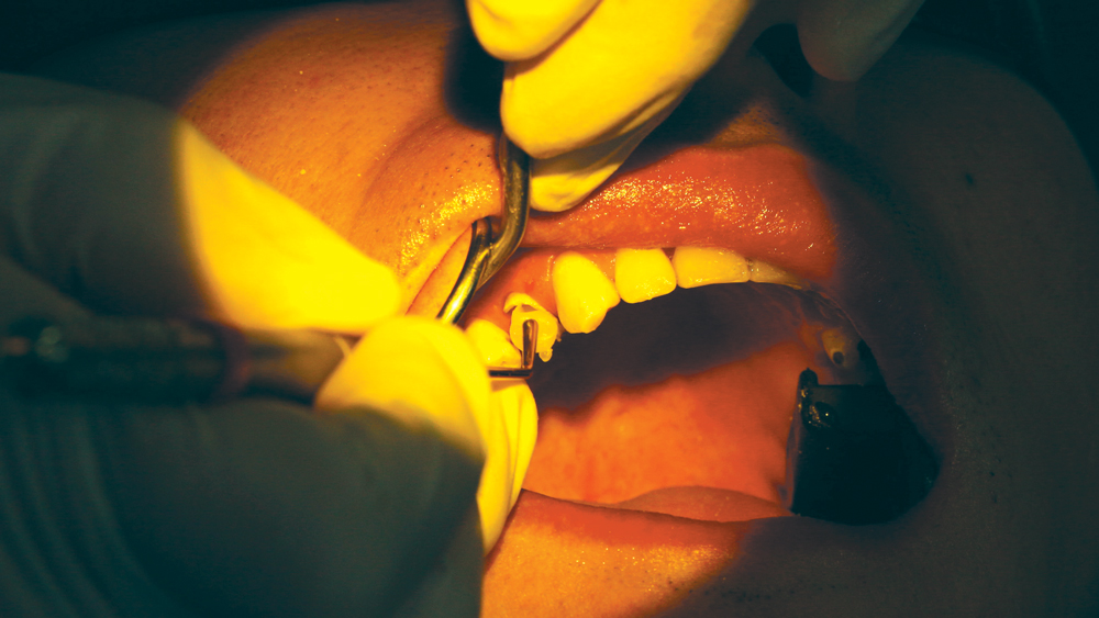
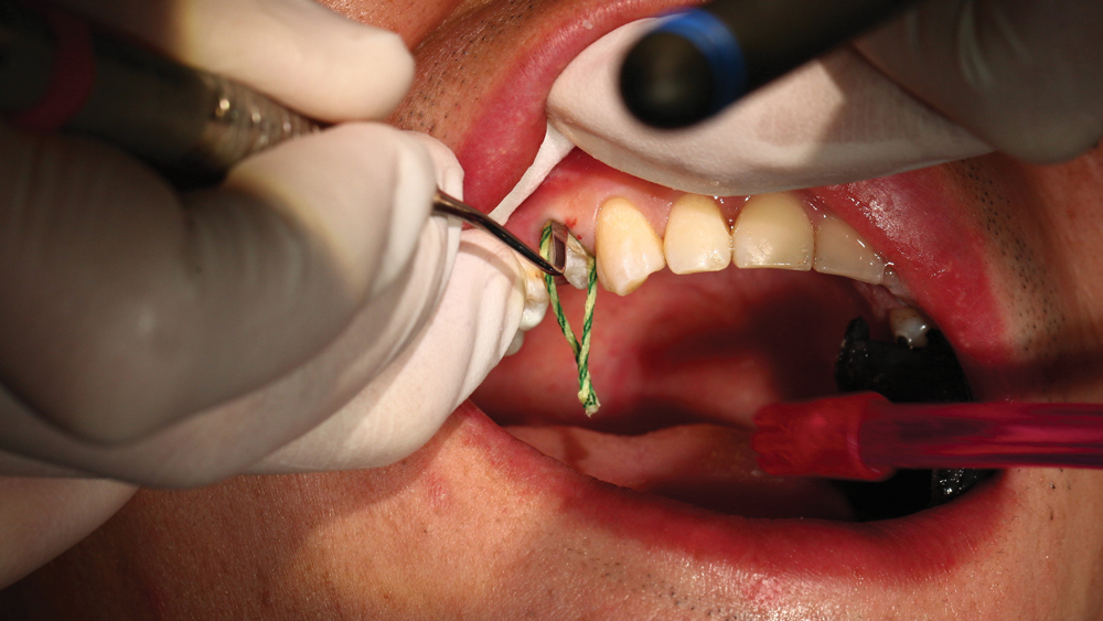
Figures 9a, 9b: The second cord that was placed was a size 2 cord, which provides lateral retraction. It’s important to embed the whole cord in the sulcus. I like placing an anatomic Comprecap (Coltène/Whaledent Inc.) to provide extra pressure to the cord. After a five-minute wait, I removed the top cord and ensured there was proper separation between hard and soft tissue.

Figure 10

Figure 10: After I pulled the top cord, I made sure the first cord was still in the sulcus and hadn’t crept upward near the margins. I air-dried the area to create an ideal scanning surface and isolate the tooth.

Figure 11

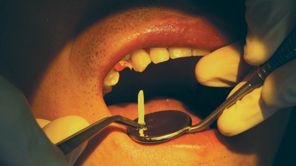
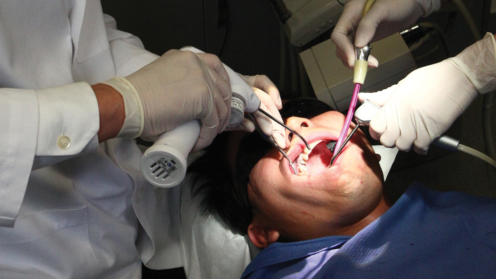
Figure 11: I used the 3M™ True Definition Scanner (3M ESPE) for this case, which requires the application of a titanium dioxide contrasting agent to the scan area. I used a mirror to retract the cheek and keep it from touching the prepped area. Tissue management and identifying the margin are always important, but even more so with digital impressions because intraoral scanners cannot yet differentiate between hard and soft tissues.

Figure 12

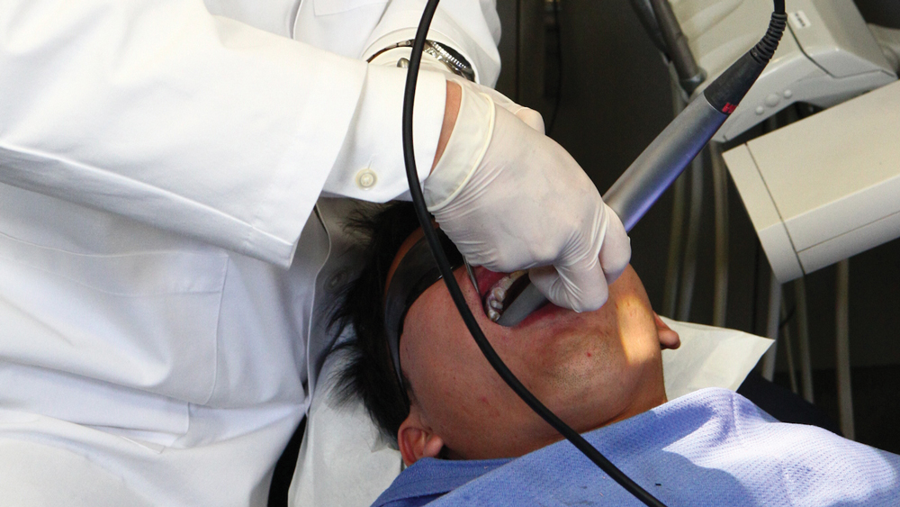
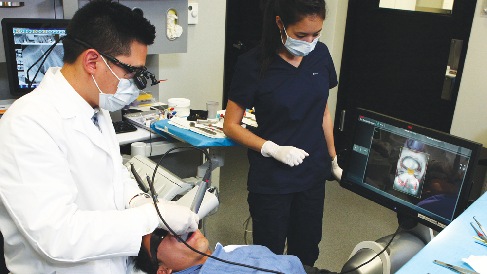
Figure 12: The small, handpiece-sized wand of the 3M True Definition makes it easy to use, but instead of looking in the mouth as the system scans, and because the scans are acquired so quickly, I find it much easier to watch the digital model generate in real time on the monitor. It requires some coordination, but with practice it becomes second nature. Digital technology allows me to fix an unsatisfactory digital scan immediately instead of waiting to hear back from the lab that a new impression is needed.

Figure 13

Figure 13: I began by scanning the occlusal — laying down the foundation — and then rotated to the buccal and lingual to ensure that all the surfaces needed were captured. Capturing at least one tooth to the mesial and one tooth to the distal helps the design software establish a good proposal. After the maxillary scans, I scanned the same aspects of the opposing teeth on the other arch. Our third set of scans were of the buccal bite, where I first verified the patient was in centric occlusion before activating the scan. Neglecting to verify centric occlusion before activating the scan can compromise the design of the restoration.

Figure 14

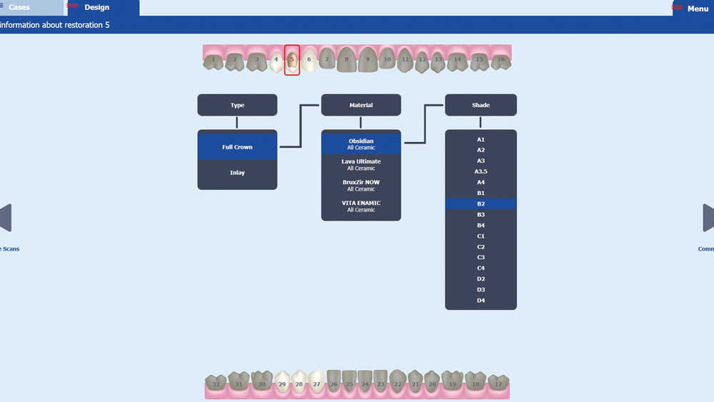
Figure 14: Following the scanning process, the resulting STL file was imported into the fastdesign™ Software, where the user is prompted to select the restoration type, desired material and shade. This case called for a full-coverage Obsidian crown in a shade B2.

Figure 15

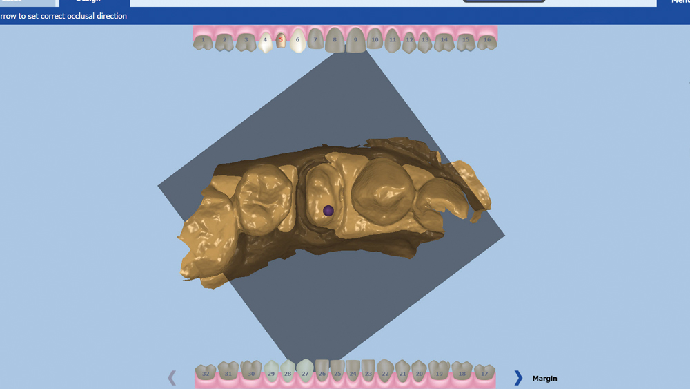
Figure 15: The first step of the design process is to identify pertinent information to help the software orient the scan. This is done by indicating the occlusal direction.

Figure 16

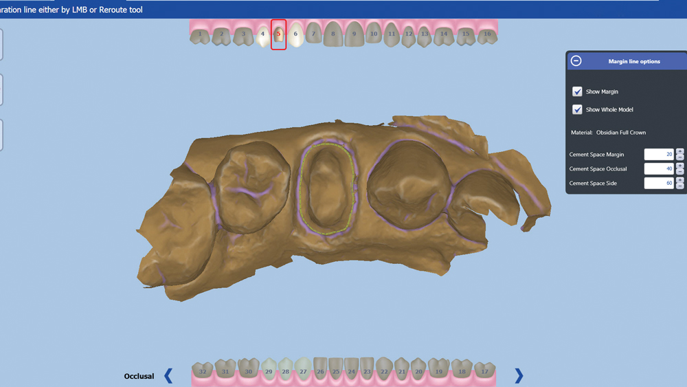
Figure 16: Next is marking the margin. Because I spent the extra time to prepare the margins and expose them with the Two-Cord Impression Technique, the software had an easy time automatically identifying the margin and I did not have to make any corrections.

Figure 17

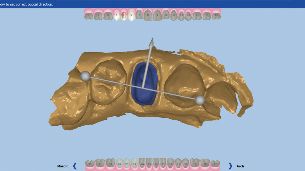
Figure 17: I then identified the buccal direction by clicking and dragging the gray arrow.

Figure 18

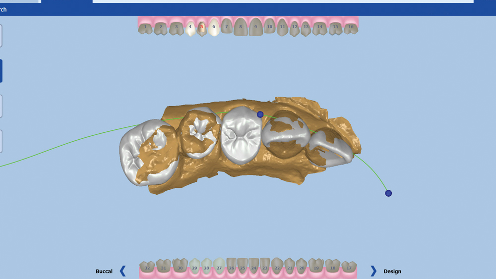
Figure 18: With the information provided from the previous steps, the software selects a design proposal from a proprietary library of tooth morphology to best match the surrounding dentition.

Figure 19

Figure 19: At this point, I have access to the move/rotate/scale tool that allows me to make larger changes to the design if needed. The design proposal did not need any large changes, so I continued to the next stage.

Figure 20

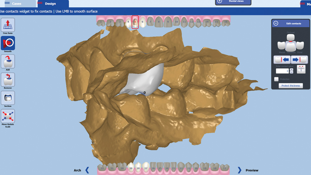
Figure 20: On screen, I like to bring up the prepped model and opposing model together, and verify that the cusp tip on the lingual of the restoration matches up with the fossa of the opposing premolar, ensuring the proper functional position.

Figure 21

Figure 21: Then, I focus on minor esthetic changes because the library of tooth morphology does a good job of finding the ideal design, but allows adjustment of cusp position or shape. This patient’s second premolar had a unique cusp shape, so I used the Free Form tool to mimic the patient’s natural dentition. Doing the design in-house allows me to make esthetic changes in real time while the patient’s specific anatomy is still fresh in my mind.

Figure 22a
Figure 22b

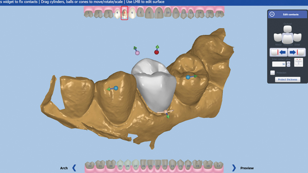
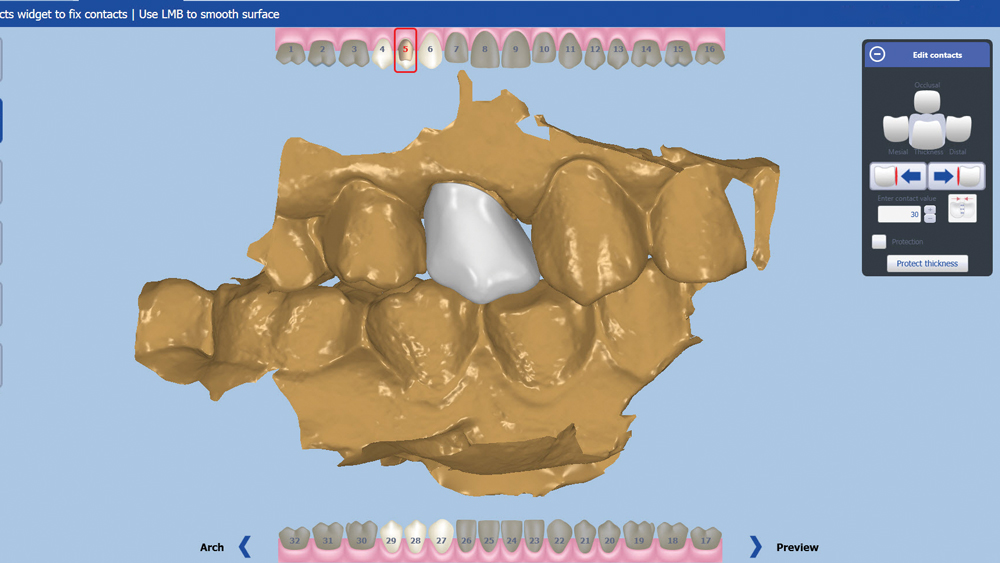
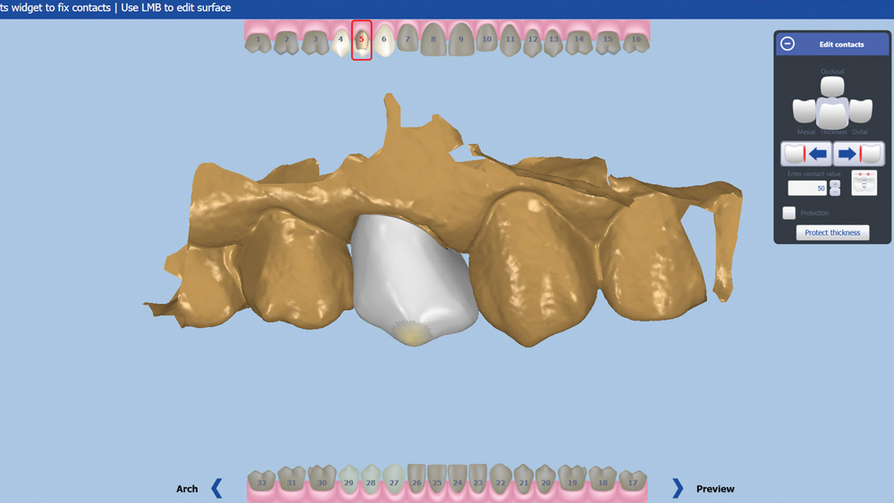
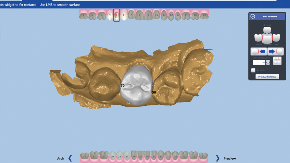
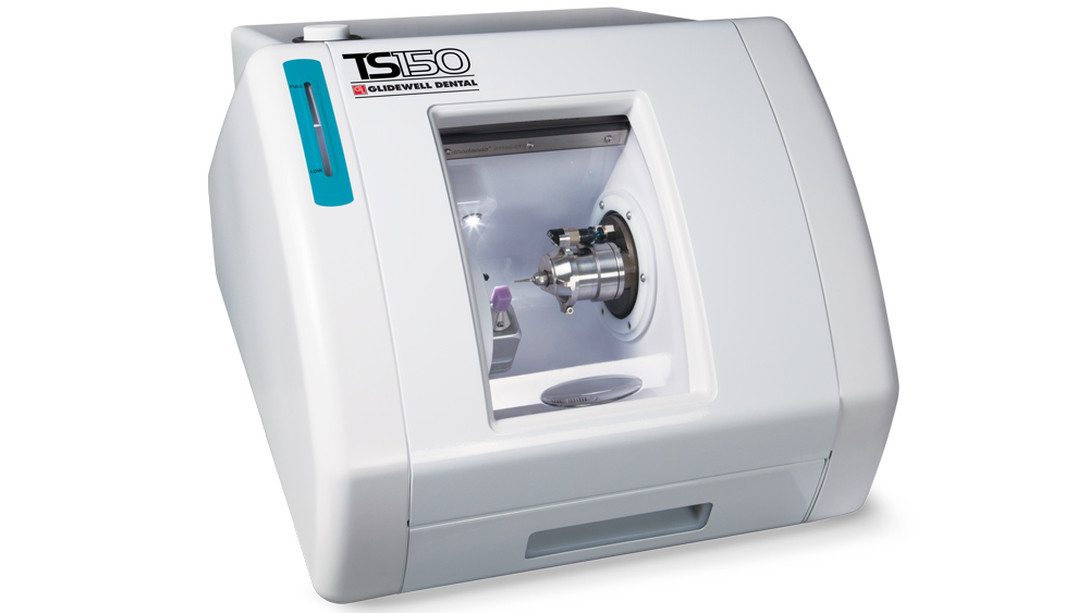
Figures 22a, 22b: Once I finished touching up the finer details, I moved onto the next stage to check the contacts. I look at the occlusal contacts and set those to my preferred parameters for each material. I then set the proximal contacts. An advantage of CAD/CAM is that each clinician can choose his or her own personal preference when setting up contact values and parameters to enter into the software. All that is needed now is to position the sprue on the restoration and send the file to the TS150™ chairside mill (IOS Technologies, Inc.).

Figure 23

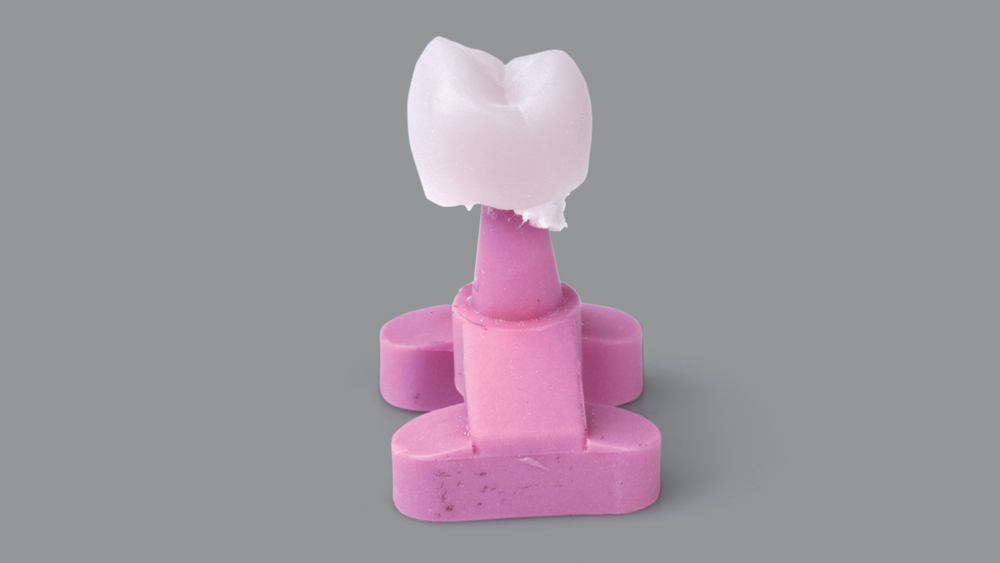
Figure 23: I placed a shade B2 Obsidian block inside the mill and initiated the milling process. After about a 13-minute milling cycle, the restoration was ready to be desprued.

Figure 24a
Figure 24b

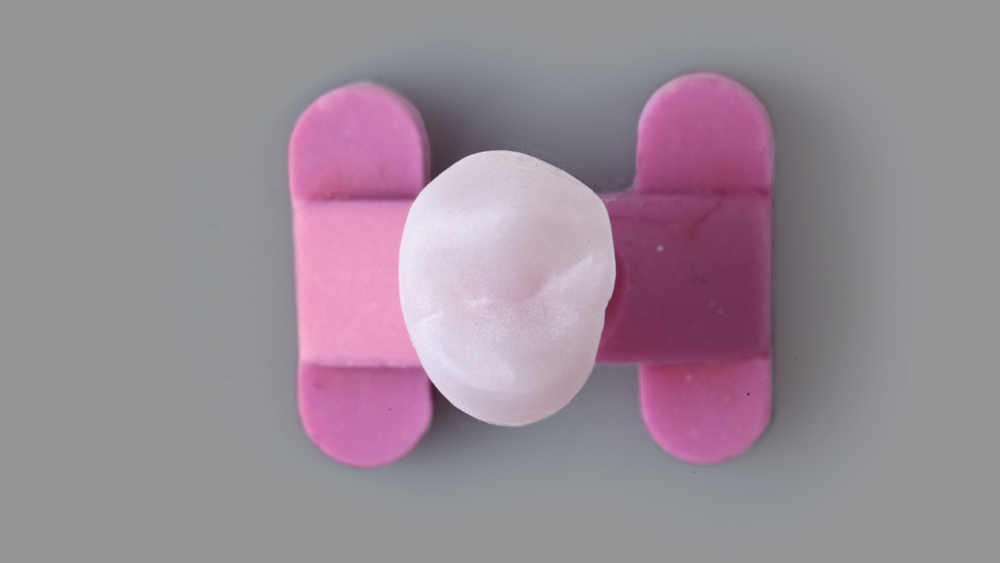
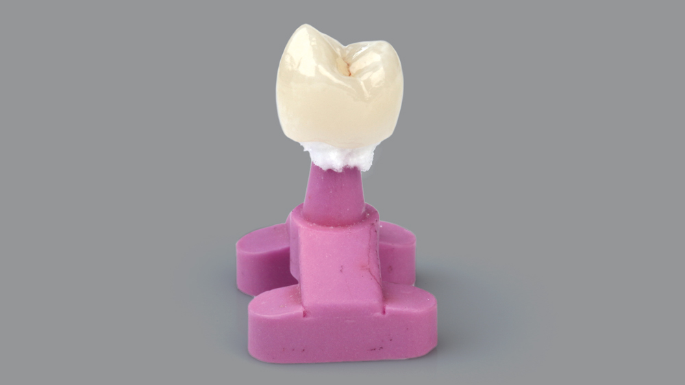
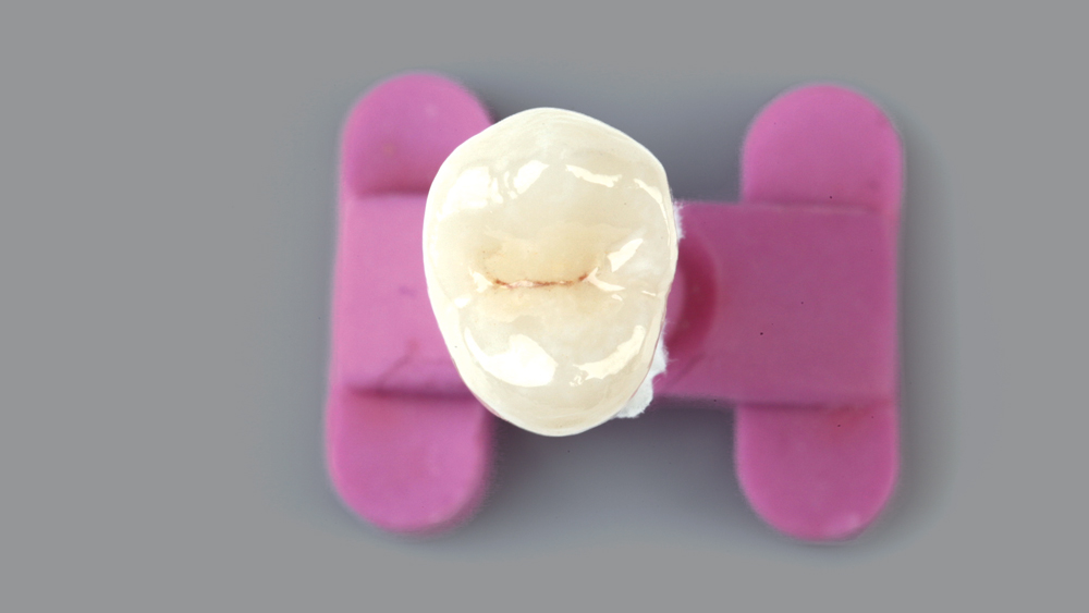
Figures 24a, 24b: Obsidian requires a 20-minute firing cycle before placement, so in this pre-crystallized state the crown can be tried in and adjusted, though there are typically very few adjustments required, if any, thanks to the precision of CAD/CAM technology. I like to take advantage of the mandatory firing cycle and enhance the esthetics further with some stain and glaze. With the patient present, I’m able to custom characterize and match the adjacent dentition with different colored stains. I applied B stain to the middle and cervical thirds to increase the hue and chroma, brown stain in the central groove for added depth, and white stain along the occlusal peripheral rim to increase value in these areas.

Figure 25a
Figure 25b

Figures 25a, 25b: Following the firing cycle, I tried in the crown once more and verified the proximal contacts and margins were optimal. I began by treating the intaglio surface with 5 percent hydrofluoric acid, and after the recommended 10 seconds, I rinsed off the etch. Next, I used Monobond® Plus (Ivoclar Vivadent; Amherst, N.Y.) to act as a coupling agent that allows the cement to adhere to the crown.

Figure 26

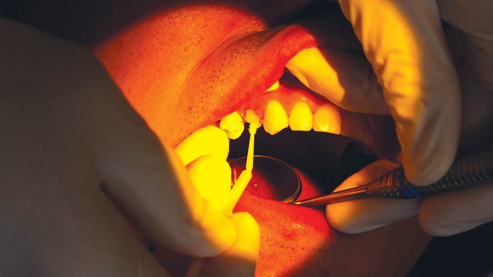
Figure 26: In preparation for bonding, I ensured the tooth was dry and free of contamination.

Figure 27a
Figure 27b

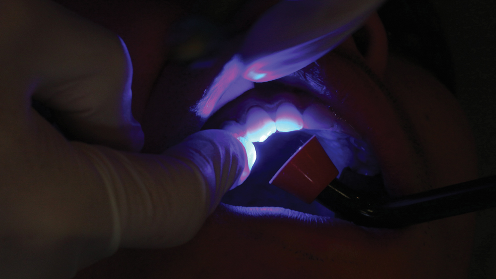
Figures 27a, 27b: I then applied RelyX Unicem, seated the crown, tack-cured the buccal and lingual, and removed the excess material.

Figure 28a
Figure 28b

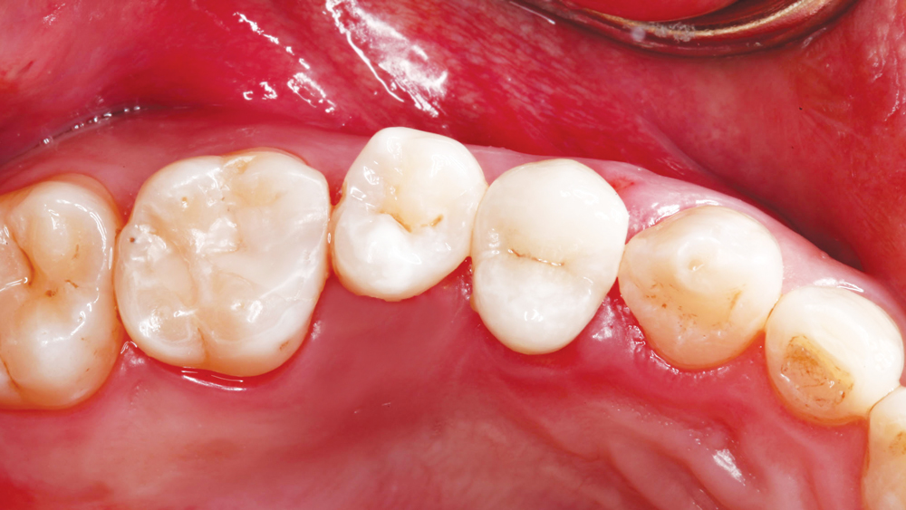
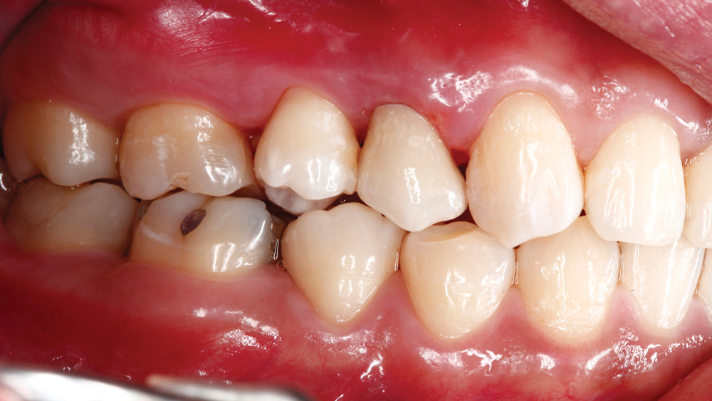
Figures 28a, 28b: The occlusion was verified following the seating of the crown, and no adjustments were necessary. Here, Obsidian offered a high-strength and highly esthetic restorative option that was delivered in one day. The materials of today are leaps and bounds ahead of those of the past; they actually look like teeth now. While it is possible to fabricate a traditional PFM and make it look natural, these new monolithic materials offer superior strength and easier-to-attain esthetics. We have the technology and the materials to create excellent crowns, not just in laboratories but in the clinician’s office as well.


We have the technology and the materials to create excellent crowns, not just in laboratories but in the clinician’s office as well.