Restorative Photo Essay: The IOS FastScan® for an Anterior BruxZir® Bridge

August 6, 2010
 image
Michael DiTolla, DDS, FAGD
Restorative Photo Essay Cover image

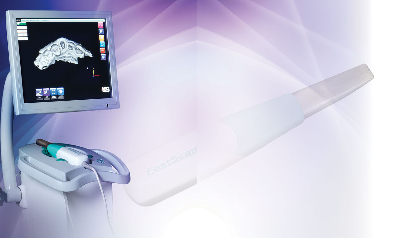
For the photo essay that follows, I wanted to highlight a case that demonstrates some of the techniques I use on a daily basis, while showing a few new techniques derived from our most recent clinical R&D efforts. The case begins with the Rapid Anesthesia Technique and then utilizes the depth-cut based Reverse Preparation Technique. Next, we use a BioTemps® provisional to create an ovate pontic receptor site. After utilizing the Two-Cord Impression Technique, we take a digital impression with the IOS FastScan® from IOS Technologies (San Diego, Calif.). The anterior bridge is then milled without a model using BruxZir®, a solid zirconia material primarily used for posterior teeth. We have received many requests from dentists who have wanted to use BruxZir as an anterior bridge material, so I was looking forward to seeing what type of esthetic result we could achieve on this first attempt.

Figure 1

Figure 1: The Rapid Anesthesia Technique was originally created for posterior teeth, specifically lower molars. It came from a desire to be able to anesthetize individual mandibular molars without having to give a lower block. Lower blocks are the injections most likely to be missed by dentists; they also have the longest onset. The ability to quickly and painlessly anesthetize individual lower molars is a huge benefit to the general dentist. The first step is to place the PFG Light topical anesthetic (Steven’s Pharmacy; Costa Mesa, Calif.) in the sulcus using an Ultradent syringe with a metal Dento-Infusor® tip (Ultradent Products; South Jordan, Utah). The PFG Light is left in the sulcus for 30 to 40 seconds, then rinsed off.

Figure 2

Figure 2: The 30-gauge extra short tip is connected to the STA® System (Milestone Scientific; Livingston, N.J.), and a carpule of Septocaine® (Septodont; Lancaster, Pa.) with 1:200:000 epi is placed in the sulcus using the tip of the needle without penetrating the attachment. I step on the foot pedal and give two to three drops of anesthetic in the sulcus, allowing it to soak for five to 10 seconds. At this point, I step on the foot pedal again to start the flow of anesthetic, and I advance the needle tip through the attachment until I contact bone. Next, I give one-half to two-thirds of the carpule while the machine confirms that I am in the PDL with visual and audio prompts.

Figure 3

Figure 3: To remove the Maryland bridge, I cut through the connectors with a Razor™ Carbide bur from Axis Dental (Coppell, Texas). Cutting through this all-composite bridge is easy for the Razor, and I routinely use it to cut through PFMs. In the past, I would cut through porcelain with a diamond and then switch to a carbide to cut through the metal coping. However, the cutting flutes of the Razor allow it to smoothly cut through porcelain and metal, simplifying the procedure.

Figure 4

Figure 4: To prevent aspiration of the pontic, I cut through one interproximal contact and then grab the pontic with forceps and snap it off. A dentist once told me the story of a patient aspirating a Maryland bridge pontic, and he cut through the second contact and the pontic flew free.

Figure 5

Figure 5: As often happens, the tissue underneath the pontic was chronically irritated and bleeding from being hit with water spray. Patients can tell you they use a floss threader nightly, but the truth is always revealed when the pontic is removed. Viscostat® (Ultradent Products) is used to keep things clean and dry.

Figure 6

Figure 6: A plain Ultrapak® #00 cord (Ultradent Products) is “flossed” by hand on the mesial and distal, leaving a small amount of cord on the facial. I use a straight, non-serrated cord packer to place the cord in the sulcus on the facial. The two ends of the cord are cut on the lingual so they will sit flush in the sulcus.

Figure 7

Figure 7: Once the #00 cord is packed, it should disappear into the base of the sulcus. We then move on to the next step of the Reverse Preparation Technique. The 801-021 round bur is used to half its depth to ensure adequate gingival reduction, and we cut the initial margin at the same time. This technique leads to simple, beautiful and consistent margins.

Figure 8

Figure 8: The next step of the Reverse Preparation Technique is the incisal edge depth cut. Because we are going to restore these teeth to the length they are now, we need to reduce 2 mm in order to give our technicians room to create a natural incisal edge. This 2 mm depth cutter is self-limiting to ensure you don’t overprepare.

Figure 9

Figure 9: You can clearly see the 2 mm incisal edge depth cut on tooth #8. I use the 1.5 mm depth cutter on tooth #10 at the junction of the incisal third and middle third. This junction tends to be an area dentists chronically under-reduce, which leads to facially prominent crowns that are too thin to be esthetically pleasing.

Figure 10

Figure 10: At this stage you can see all of the depth cuts on tooth #8: the 2 mm incisal edge depth cut, the 1.5 mm depth cut and the incisal/middle third junction, and the gingival reduction/deep chamfer from the 801-021 round bur. Now the prep becomes a race; we know how much we have to reduce, so it’s a matter of removing tooth structure in a timely fashion.

Figure 11

Figure 11: The 856-025 bur is my workhorse bur. I love super-coarse diamonds in large diameters — what a great way to shape a tooth. Small-diameter burs have a tendency to sink into the tooth (especially buildup material) because they don’t have the surface area to support their own weight. I use the 856-025 for the incisal and facial reductions, and interproximal areas where it fits, and the 856-018 for tight interproximal areas.

Figure 12

Figure 12: The 379-023 football bur is used to reduce the lingual surface. Because the football bur is convex, we use it to develop a desirable concave reduction on the lingual. Typically, we don’t place depth cuts on the lingual of anterior teeth because we use the mandibular anterior teeth as a guide of how much we have reduced and how much clearance we need.

Figure 13

Figure 13: My favorite part of the Reverse Preparation Technique and the best thing about electric handpieces is the ability to turn down the rpm to 5,000 and turn off the water. My KaVo ELECTROtorque (Charlotte, N.C.) has all its torque at 5,000 rpm but spins slowly enough that I can turn off the water without overheating the tooth. For once, I can see enough to smooth the margin well.

Figure 14

Figure 14: At this point I know the preps are finished because the depth cuts are gone. Before I developed this technique, I used to prep teeth and guess when they were done. I always request a prep guide with my BioTemps to see if I missed a spot, although this is highly unlikely with depth cuts. Now I know the BioTemps will seat completely.

Figure 15

Figure 15: I can see that the BioTemps will go down all the way once I remove the soft tissue interference in the area of the pontic. I told the lab I would develop an ovate pontic receptor site, and that I wanted them to socket the model 4 mm from the gingival margin of the old Maryland bridge pontic.

Figure 16

Figure 16: Because I hadn’t given an infiltration to prepare the two teeth, I needed to anesthetize the soft tissue in the pontic area. Again, the STA System was used with Septocaine to provide the anesthesia. Because we are in tissue that is tightly bound to the periosteum, I am using the STA speed, the slowest on the unit.

Figure 17

Figure 17: I have done plenty of ovate pontic receptor sites with a hard tissue laser, but I was in an old-school mood. I used the 801-021 round bur and removed 2 mm of tissue and 1 mm of bone. Biologic width is only 2 mm in a pontic area because we do not have to have the 1 mm sulcus depth that we typically have around a tooth.

Figure 18

Figure 18: Now the BioTemps bridge seats completely. I have removed the soft tissue interference and created a situation for the new pontic in which it appears to be growing directly from the tissue. The BioTemps provisional has helped me remove adequate tissue and will help shape the tissue during the healing process.

Figure 19

Figure 19: With the ovate pontic receptor site complete, it is time to prepare for the final impression. This begins with the placement of the second, or top, cord. This cord is a #2E Ultrapak cord from Ultradent. The top cord provides retraction for the impression material, or in this case, for the digital impression.

Figure 20

Figure 20: Oftentimes, once the top cord is placed you are able to see some irregularities on the margins you couldn’t see when the marginal gingiva was adjacent to the preparation margin. Again, I turn down the handpiece to 5,000 rpm, turn off the water and smooth the margin one more time so there is no doubt as to the finish line.

Figure 21

Figure 21: Two Roeko Anatomic Comprecaps (Coltène/Whaledent; Cuyahoga Falls, Ohio) are placed and the patient is instructed to bite down for eight to 10 minutes. The new Comprecaps have interproximal cutouts to avoid blunting the papilla, especially in a case where a pontic is present. Without the support of the pontic in place, it is easy to damage the papilla if you aren’t careful.

Figure 22

Figure 22: After eight to 10 minutes, the Comprecaps are removed from the sulcus, as is the #2E (top) cord. The #00 (bottom) cord remains in place during the entire impression procedure and often until the provisional has been cemented. A light coat of IOS spray is applied to the preps, the pontic area and the adjacent teeth.

Figure 23

Figure 23: The IOS FastScan is the only system in which you hold the wand still while the camera moves within the wand. It is counterbalanced so that as the camera moves across its 40 mm path, you are not able to feel it moving. This single capture is equal to four or five still frames taken with another system. This first capture is straight down from the incisal edge.

Figure 24

Figure 24: The wand is rotated slightly toward the facial to capture the facial view of the prepared teeth. Again, the wand is held still while the lens moves inside the camera. It takes the IOS FastScan approximately one second to capture the information needed.

Figure 25

Figure 25: The wand is now rotated to the lingual for the final scan of the prepared teeth. The computer will then stitch these three views together (incisal, facial and lingual) to complete the digital model. As long as you treat the tissue well and don’t have any bleeding, this is a stress-free procedure.

Figure 26

Figure 26: If desired, you can capture two interproximal shots to give the computer a better idea about the contours of the adjacent teeth. Rotate the camera 45 degrees from its normal anterior orientation to capture two images of the proximal surfaces of the adjacent teeth.

Figure 27

Figure 27: My assistant and I will typically use lip retractors in the posterior, but in the anterior, finger retraction is often enough. We powder the lower anterior teeth in order to scan the bite to create the virtual digital model. The upper teeth do not need to be re-powdered if they have been kept dry.

Figure 28

Figure 28: With the patient biting into maximum intercuspation and with the teeth powdered, the scanner is held parallel to the facial surfaces of the teeth for scanning. The computer can now take the upper and lower digital impressions and articulate them properly.

Figure 29

Figure 29: Now that I am finished scanning the prepped arch and the bite relationship, my assistant scans the opposing arch. More often than not, she will have done this before I ever walk into the room. In California, RDAs with an EF license are authorized to take the final impression, whether digitally or conventionally.

Figure 30

Figure 30: Because this is the opposing arch with no preparations, my assistant can capture all the information in two scans: a facioincisal and a lingoincisal. Working alone, my assistant uses lip retractors to ensure the lips don’t touch the previously powdered teeth.

Figure 31

Figure 31: We took the shade at the beginning of the appointment but neglected to photograph it. If you are using something as simple as the VITA Easyshade® Compact (Vident; Brea, Calif.), avoid the common mistake of waiting until the teeth are dehydrated to take the shade; do it pre-anesthesia. 

Figure 32

Figure 32: The VITA Easyshade Compact shows a shade of B2 for the adjacent tooth (#11). We try to take the shade smack dab in the middle third, with as much of the tip in contact with the tooth as possible. You can take the shade in the cervical third and the incisal, but only measuring the middle third is adequate.

Figure 33

Figure 33: My assistant likes to place dental floss around bridges with ovate pontic sites to ensure excess cement is removed from around the bridge. This is especially important when you have prepared an ovate pontic receptor site, as we have done here. Cement that stays in the site of the surgery will have an adverse effect on the tissue.

Figure 34

Figure 34: The BioTemps provisional has been cemented into place and all of the excess cement has been removed. My assistant left a small open embrasure between teeth #8 and #9 to ensure we don’t blunt the papilla. Knowing patients won’t use a floss threader around temps, I like to leave the gingival embrasures open and have them swish with Tooth and Gums Tonic® (Dental Herb Company; Boca Raton, Fla.) to keep the area clean.

Figure 35

Figure 35: A look at the opposing model as captured by the IOS FastScan scanner. Using the two scans we took, we are able to clearly visualize the facial, lingual and incisal characteristics. Dental assistants in all states can take this scan because they’re already permitted to take opposing alginate impressions, for example.

Figure 36

Figure 36: Here is the prepped arch as captured by the IOS FastScan scanner. In addition to capturing the information of the abutment teeth, the scanner was also able to accurately read the internal contours of the ovate pontic receptor site. Notice how the incisal half of the preparations angle toward the lingual because of the position of the 1.5 mm depth cut.

Figure 37

Figure 37: A look at the bite registration as captured by the IOS FastScan. In a sense, bite registration is more straightforward digitally because you are able to visually verify it as the patient bites in maximum intercuspation. Depending on your bite registration technique, it is difficult at times to verify whether the patient is truly in maximum intercuspation.

Figure 38

Figure 38: Here is a BruxZir Solid Zirconia anterior bridge at cement cleanup. We use RelyX™ Luting Cement Plus (3M™ ESPE™; St. Paul, Minn.) because of its bond strength to dentin, ease of use and simple cleanup. If you’ve ever had to cut off crowns cemented with a resin-reinforced glass ionomer like RelyX before, you know it’s plenty strong.

Figure 39

Figure 39: This photo was taken on the day of cementation, with a retracted smile. This BruxZir bridge is solid zirconia and has no porcelain on the facial; it has just been polished and glazed. It might not be the most beautiful anterior bridge in the world, but it just might be the strongest. The ovate pontic site turned out decent as well, which is sometimes difficult to achieve in a retracted photo.

Figure 40

Figure 40: Here, we see a nonretracted smile on the day of cementation. You can probably tell that by taking the shade on tooth #11, we ended up matching the bridge to that tooth better than to tooth #7. Tooth #8 could have been stained to match #7, but then #8 might not have matched #9. Ensuring the centrals match is usually job No. 1 in smile design.