Holiday Hours Update: In observance of the upcoming holidays, our Contact Support Centers will be open on December 24 until 3:00pm. We will be closed on December 25 and January 1. Wishing you and yours a Merry Christmas and Happy New Year!

×

Digital Communication of Critical Cosmetic Restorative Guidelines
November 27, 2012
Bill C. Strupp, DDS image
William C. Strupp Jr., DDS, FAACD
Digital Communication of Critical Cosmetic Restorative Guidelines

One of the most important elements of a cosmetic restorative case is the horizontal plane of the case (HPC). The HPC is defined as the plane that the incisal edges of the anterior restorations should follow relative to specific landmarks of the face. Ninety percent of the time, the plane can follow the pupillary line plane. The gingival plane of the anterior teeth should parallel the HPC when the gingival line is visible in the smile. Facial asymmetry and biological limitations based on anatomy dictate the reality of what is possible when matching the gingival plane to the chosen HPC.

Leaving the HPC up to chance or ignoring it often compromises the cosmetic outcome of the case. As such, it is important for the restorative dentist to define and then communicate the HPC to the laboratory and to the specialists involved in the interdisciplinary treatment of the case. When biological limitations do not exist, it is important for the laboratory and the specialists to follow the designated plane.

Analyzing and deciding on the appropriate HPC is easily done using a lip-retracted, full-face digital photograph imported into presentation software such as Apple Keynote® (Apple Inc.; Cupertino, Calif.) or Microsoft PowerPoint® (Microsoft Corporation; Redmond, Wash.). In this author’s opinion, Keynote is by far the easiest program to use.

Steps in the Digital Communication Process:

1. Take the photographs.
2. Analyze the photographs to determine the HPC.
3. Communicate the HPC to the laboratory and the specialists involved in the interdisciplinary management of the case.

Figure 1

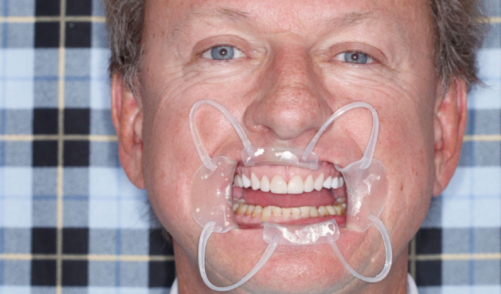
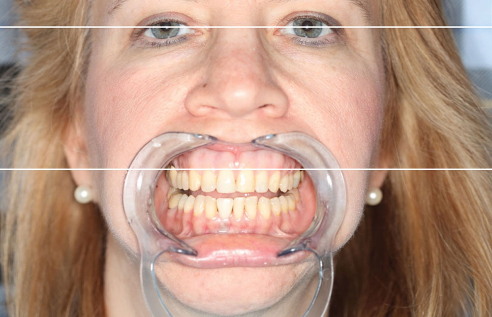
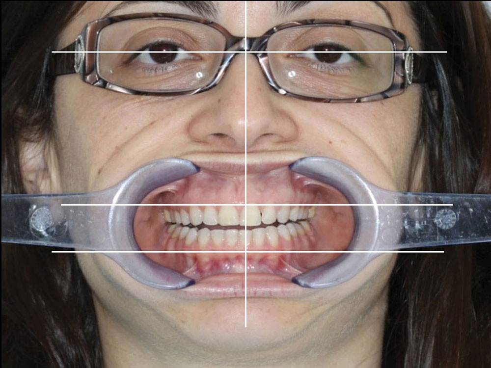
Figure 1: The retracted view full-face photograph is made with the patient standing against a wall marked with “correct” horizontal and vertical lines. The patient must not lean against the wall and should stand erect without tilting the head. The photographer should attempt to eliminate any camera tilt and to take care not to shoot the photograph at an angle from the left, right, above or below. The patient must be “square” to the camera and vice versa. The photograph is captured and then imported into Apple Keynote.

Figure 2

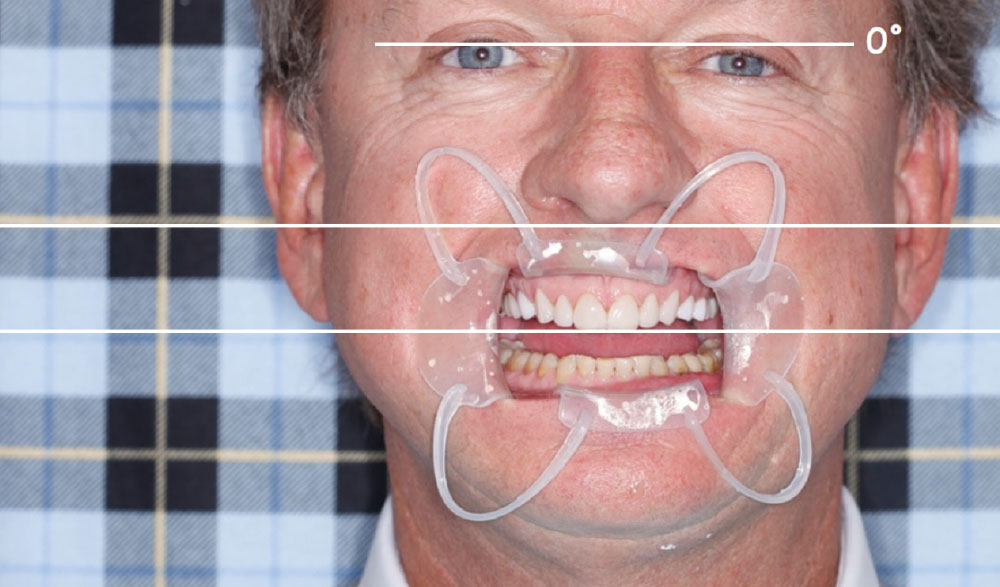
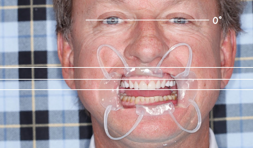
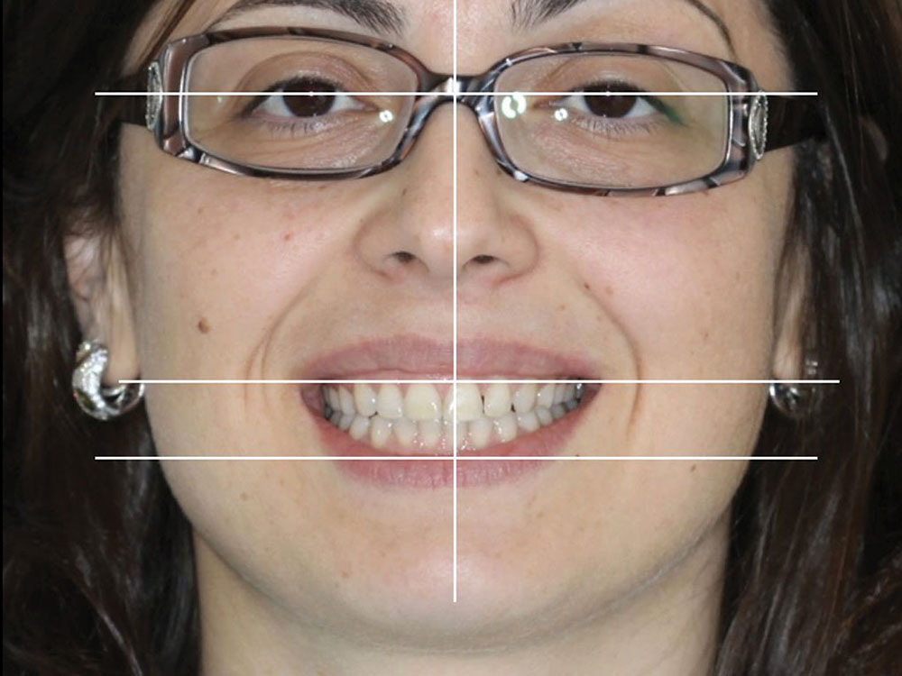
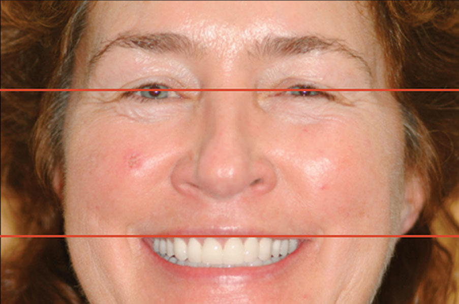
Figure 2: The first step in analysis is to draw a 0-degree line on the photograph that extends beyond the spectral highlights — the white dots in the pupils caused by reflection of the camera flash. Other 0-degree lines can be drawn over the teeth and the gingiva to assess the horizontal plane and to determine the HPC. Analysis of these lines reveals the patient’s tilt and facial asymmetry in the photograph.

Figure 3

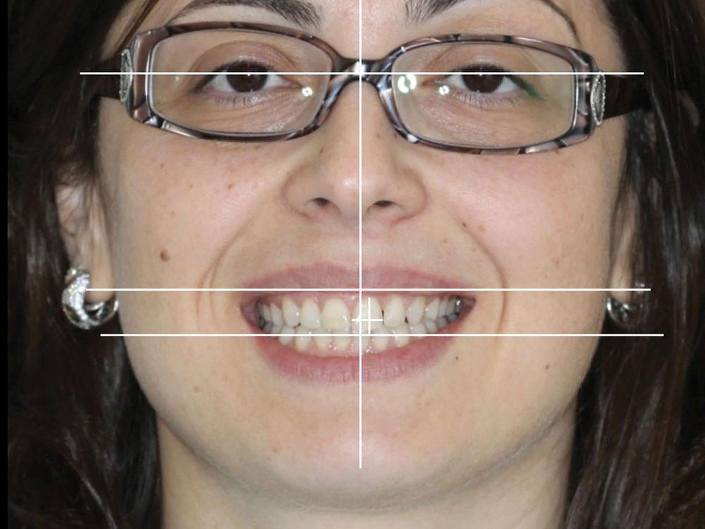
Figure 3: The photo is then “corrected” by tilting it in Keynote so the 0-degree line crosses both spectral highlights at the same point. It is now possible to draw other 0-degree lines to decide if the patient or camera was tilted, or if the patient is tilted anatomically. From these lines the ideal HPC can be determined. In this case, because the patient’s ear lobe plane anatomically matches his pupillary line, the selected HPC is the pupillary line. Further analysis of the incisal and gingival planes reveal asymmetry. If the gingival plane does not show in the full smile, that asymmetry does not require correction. If the incisal plane can be corrected without creating undue envelope of function issues, and if there is sufficient biological support available to allow a change, then it is possible in the final restorative case to change the incisal plane to match the HPC. A complete understanding of occlusion is necessary to make these determinations. This maxillary case was previously restored without paying attention to the foregoing discussion, and the cosmetic result mirrors the lack of attention to these details.

Figure 4

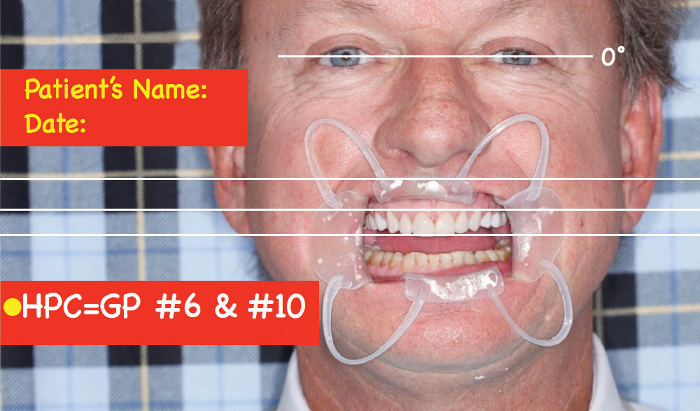
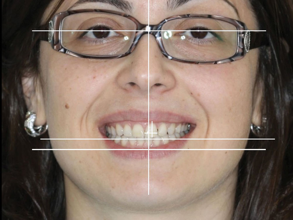
Figure 4: If the case is to be restored, communication of the HPC is necessary. This is accomplished by adding the patient’s name, date of the photograph and selected HPC to the slide. The restorative dentist selects the HPC for this case as the gingival plane of teeth #6 & #10. This slide is then printed and sent to the laboratory, as well as to the specialists if surgical correction is necessary. When a modification of the gingival plane is necessary to match the HPC, the periodontist decides if there is adequate biological support to create the desired changes, communicates this to the restorative dentist, and then matches the gingival plane to the HPC using the appropriate surgical approach and biological respect. When the case is mounted for diagnosis and treatment planning or for treatment, the laboratory trims the base of the maxillary cast to be parallel to the HPC (the gingival plane of teeth #6 & #10) and mounts the models with the base of the maxillary cast parallel to the horizontal plane of the articulator. In addition, the midline of the face should be the midline of the articulator. All diagnostic waxing, case planning and finishing of the restorative case is done on models mounted by the laboratory in this orientation.

Figure 5a
Figure 5b

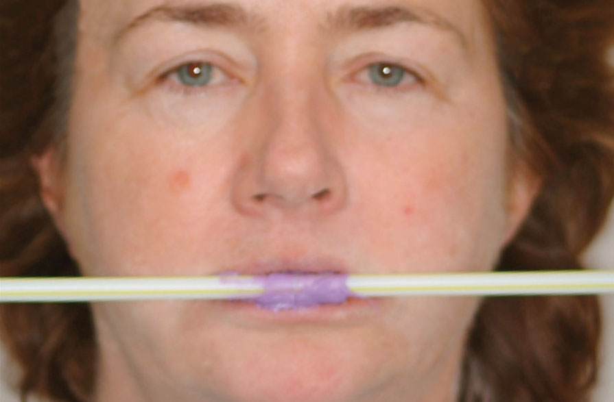
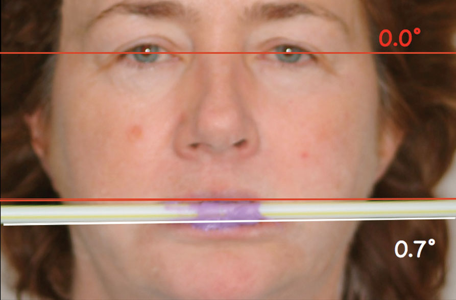
Figures 5a, 5b: Many clinicians suggest using a straw bite to record the correct HPC. Unfortunately, 99% of these bites are incorrect and lead the laboratory to mount cases incorrectly. Diagnostic waxing, case planning and finishing using an incorrect HPC is a sure way to compromise the cosmetic outcome of the case.

Diagnostic waxing, case planning and finishing using an incorrect HPC is a sure way to compromise the cosmetic outcome of the case.
Figure 6a
Figure 6b

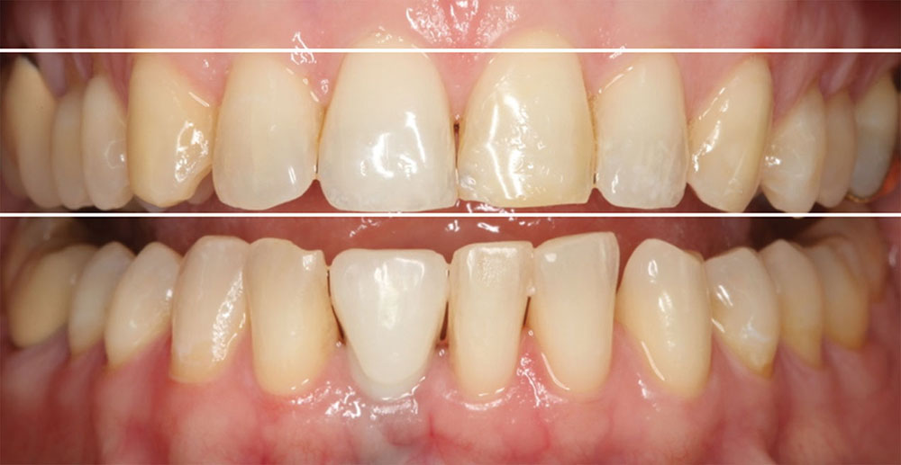
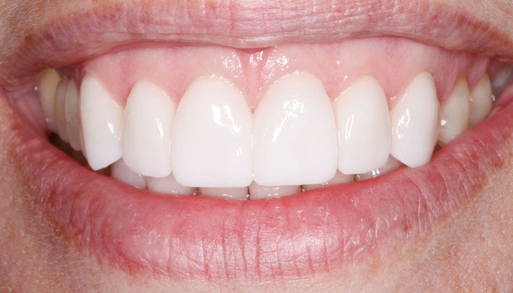
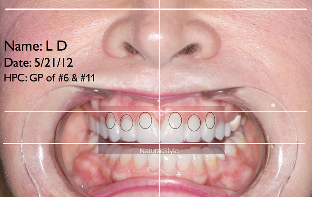
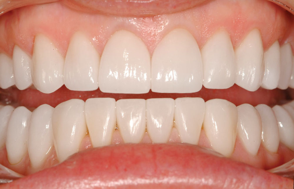
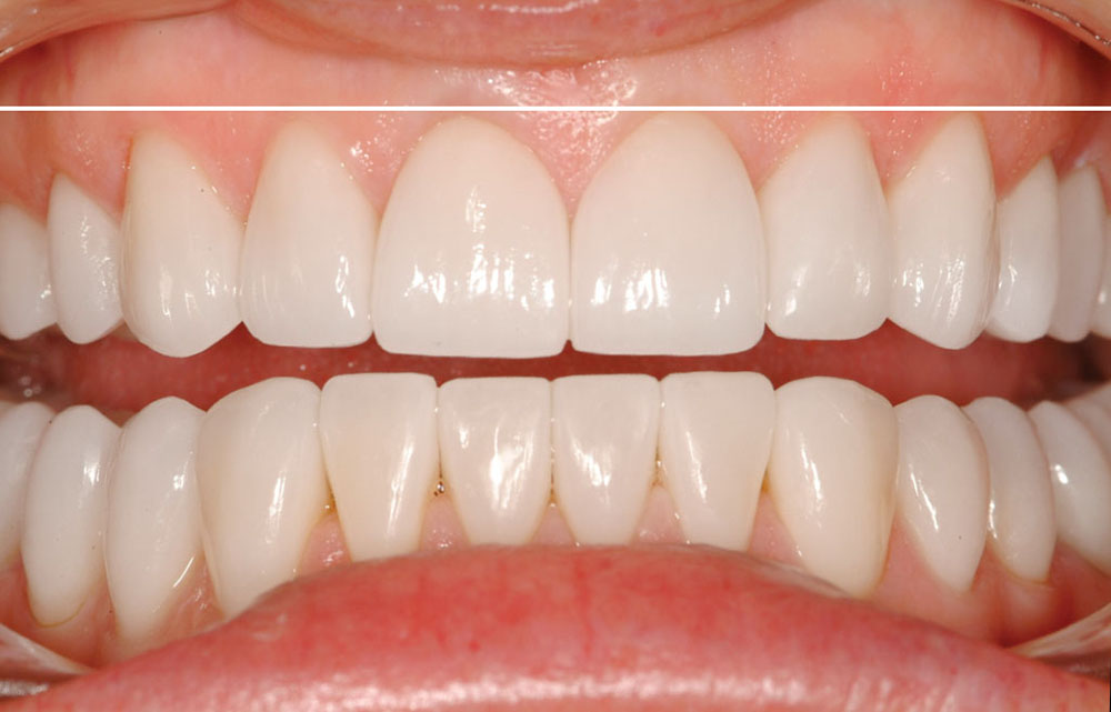
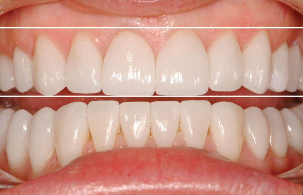
Figures 6a, 6b: Postoperative computer analysis of case photographs reveals both successes and failures, thereby helping the clinician improve communication and cosmetic results for future cases. These are preoperative photos of a missing lower central case planned for phased restorative treatment of all of the teeth over time. No periodontal surgery was done in this case because the gingival plane was not a cosmetic compromise. The chosen HPC was the gingival plane of teeth #6 & #11.

Figure 7b
Figure 7b

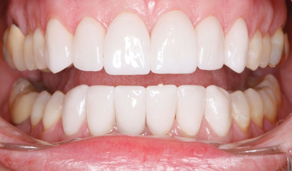
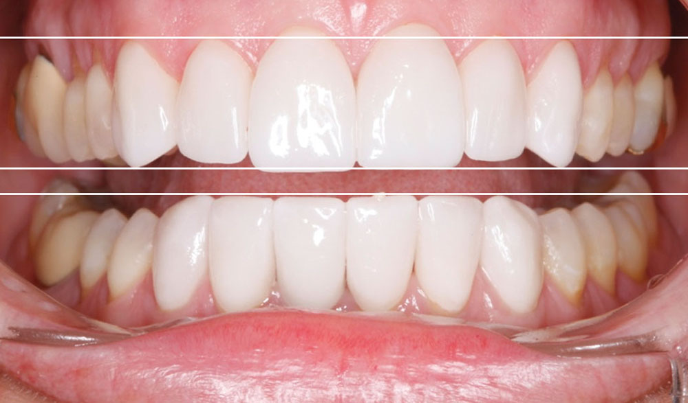
Figures 7a, 7b: The “after” photograph reveals the success and failure of the case. The incisal plane is perfectly parallel to the HPC, but the maxillary right central is 0.3 mm too long. The restorations were made of single-tooth IPS e.max® Press (Ivoclar Vivadent; Amherst, N.Y.) restorations on supragingival margins. A custom zirconia abutment was used for the missing mandibular central.

Figure 8

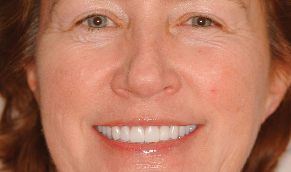
Figure 8: The short lip exposes the gingival line, and were it not within normal cosmetic limits, surgery would have been required to alter it so it would be parallel to the HPC.

Figure 9

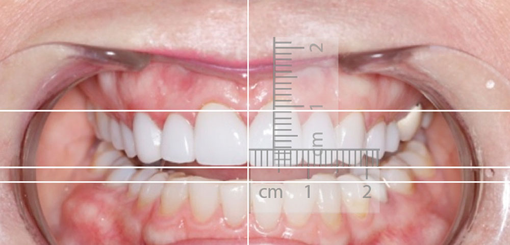
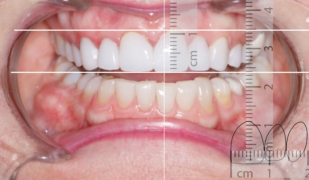
Figure 9: Keynote also allows the clinician to use innovative concepts in studying cases and communicating with the laboratory and specialists. Here, an image of a ruler was cropped and properly sized. The maxillary left central incisor was exactly 9 mm wide, so this dimension was used to size the ruler image. (Note: A known dimension must exist in the photo to properly size the ruler image.) The opacity was reduced to 20%, the image was duplicated and rotated 90 degrees, and then both images were placed over the maxillary left central to study length and width proportions.

Figure 10

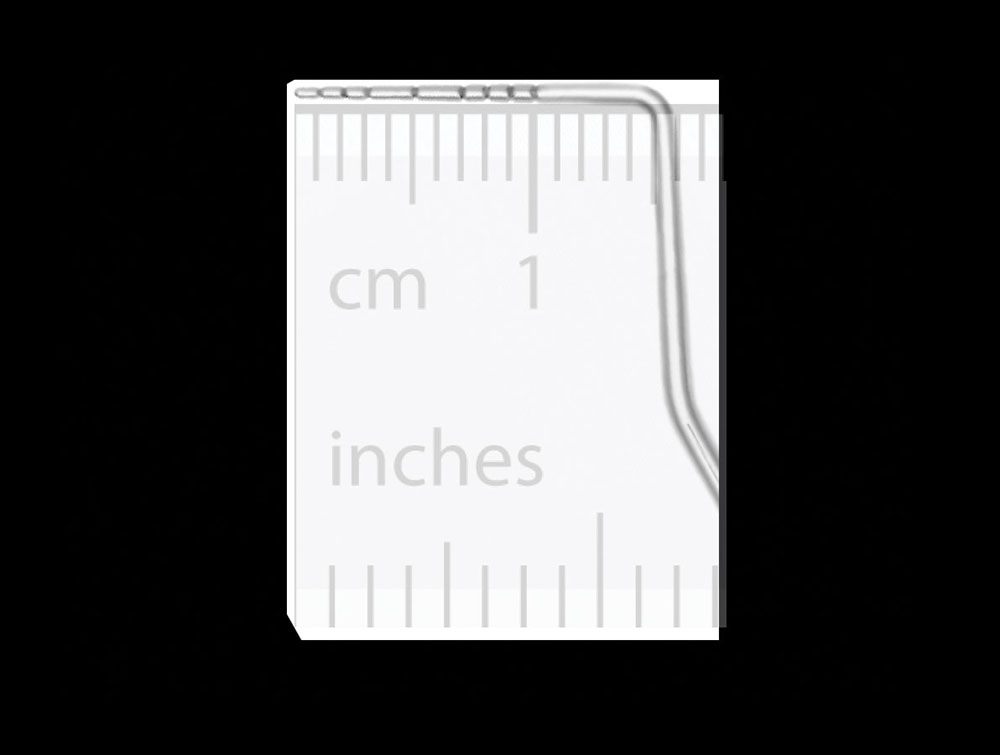
Figure 10: If a probe is placed in the same plane as the teeth and photographed in the full-face retracted view, imported overlay images (in that plane) can be properly sized to analyze length and width proportions. Knowing the exact width and length of a central incisor is the easiest way to correctly size imported images.

Figure 11

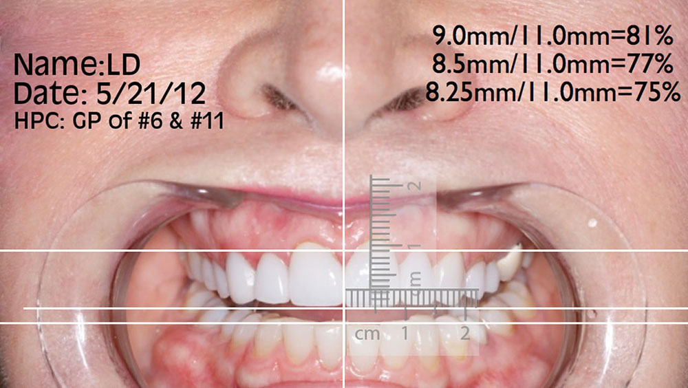
Figure 11: Calculations can be made to decide length and width proportions and to determine if those proportions are possible. It is impossible to make a tooth that is 9.0 mm wide as it emerges from the tissue be less than 9.0 mm wide. The gingival diameter of the root mesiodistally cannot be altered without drastic surgical procedures. The three dimensions depicted on this photograph can be assessed for practical application for making the final case. In this case, 75% is ideal, but probably not possible.

Figure 12a
Figure 12b

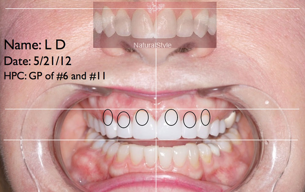
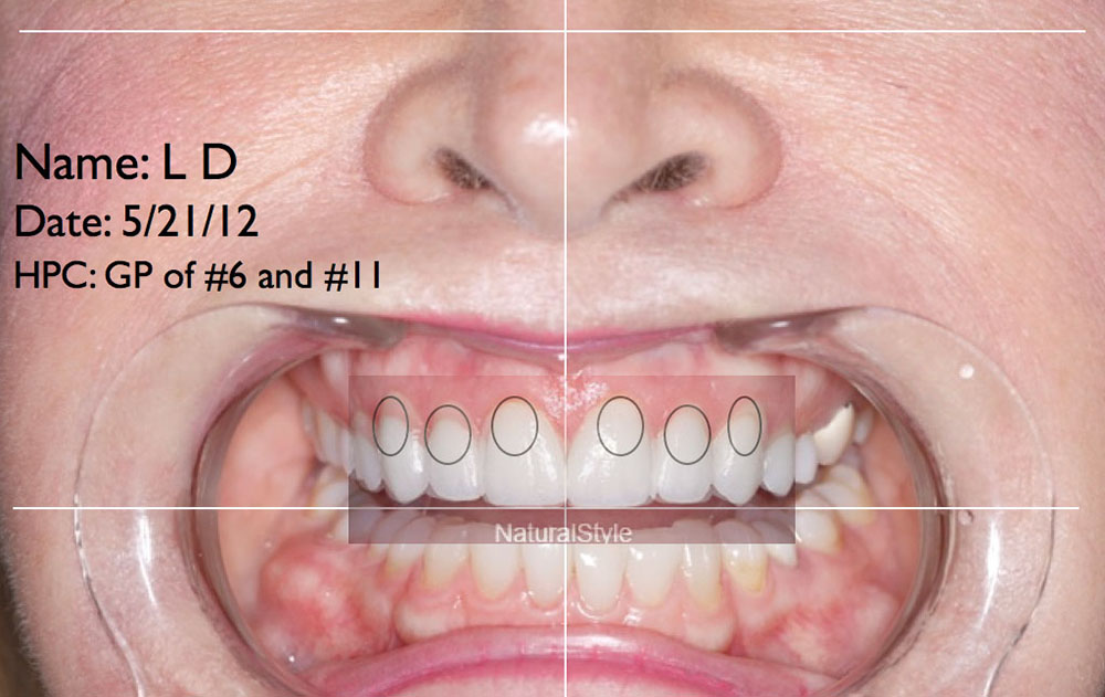
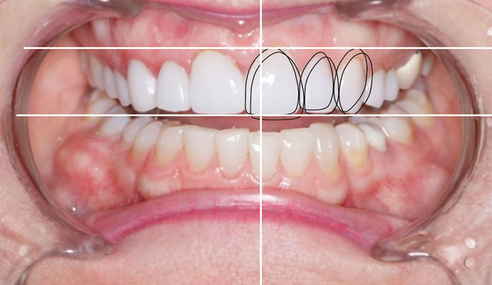
Figures 12a, 12b: Another interesting thing that can be done for communication with specialists is to draw circles at the height of the existing gingival line and then overlay an image of teeth obtained from the internet, properly sized and reduced in opacity, to evaluate where the gingival levels are and where they should be placed relative to the circles under the image. It is obvious from the circles in this image that the gingival line is not very esthetic. It is also obvious from the line drawn along the gingival line of the internet photo that the gingival line of this image is asymmetrical. The tissue on the right cuspid is receded and the tissue on the laterals is not receded enough. When the teeth are overlaid matching the incisal edges, which were ideal in length, the gingival aspect of where the tissue is and where it needs to be can be evaluated and communicated to the specialists.

Figure 13

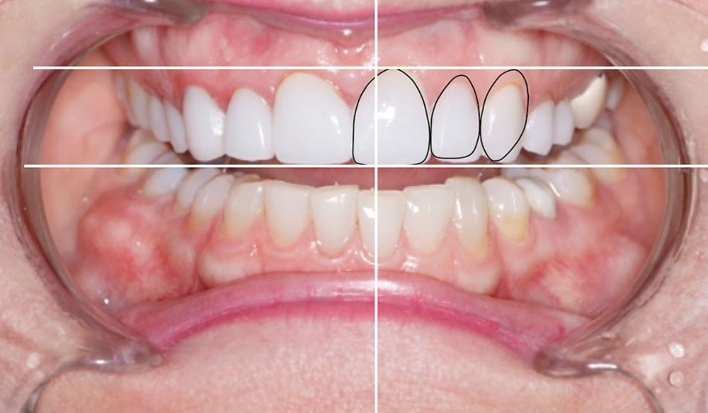
Figure 13: The circles can be moved apically into an acceptable position relative to the HPC using a 0-degree line over the central gingival line as a reference point. The height of tissue on the cuspids and centrals should fall on this line, with the laterals 1.0–1.5 mm short of the line. Once the imported image is overlaid, an analysis of what might be better cosmetically can be visualized, taking into account the gingival line issues of the imported photograph. This information can be photographically transmitted to the periodontist for proper tissue positioning, provided it is permitted biologically. Likewise, the incisal plane can be visualized and communicated to the laboratory for proper design in both the diagnostic and final phases of treatment.

Figure 14a
Figure 14b
Figure 14c
Figure 14d

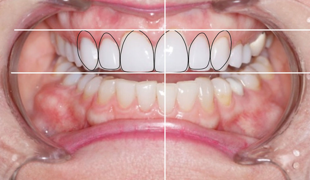
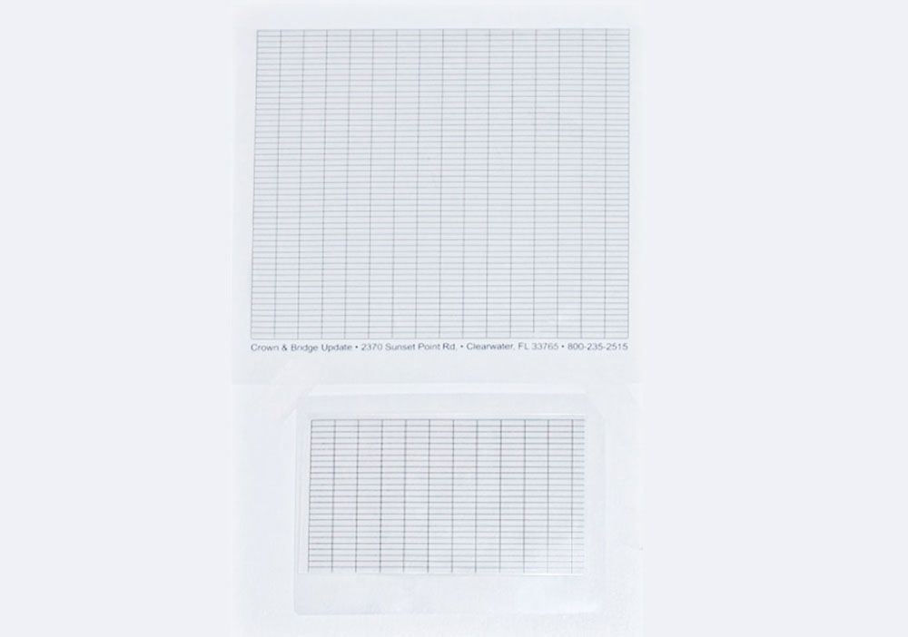
Figures 14a–14d: Instead of using imported images of teeth, outline drawings of teeth that are properly sized and proportioned can be used to evaluate the gingival and incisal planes. The outline drawing in this photo is exactly 8.5 mm x 11.0 mm, which is believed to be the most realistic size for this case. Once the outline drawing is properly sized, it is moved over the gingival line of the teeth in the correct HPC and duplicated in Keynote. It is then flipped in Keynote and the mirror image is properly positioned in the correct HPC to match the other side. Analysis of these line drawings can be helpful to the referral doctors and to the laboratory technician in managing the case. The question surgeons must answer is: “Are the desired cosmetic changes possible given the biological support that exists?” The question laboratory technicians must answer is: “Can the case be properly mounted so the quest for a HPC can be achieved?” The question for the restorative dentist is: “Will I spend the time to do all this stuff?” If the restorative dentist will not take the time to learn how to do all of these “high-tech” procedures, all is not lost. Most of the communication needed can be transmitted with the use of a Straight Smile Guide™ (Crown & Bridge UPDATE, 800-235-2515). Created for technophobe dentists, it is a quick way to analyze and communicate critical cosmetic parameters to the team.
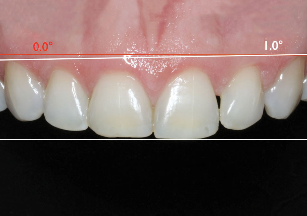
Figure 15

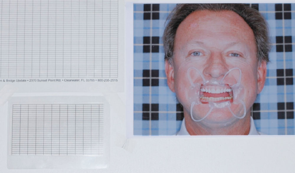
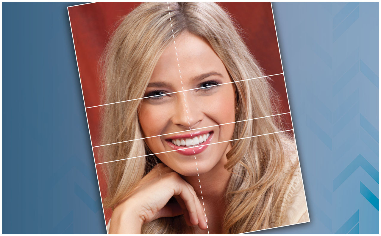
Figure 15: The Straight Smile Guide is a stiff plastic sheet with grid lines running vertically and horizontally. This guide comes in two sizes. The large size is used to evaluate the HPC by placing it over a full-face, retracted view, 8.5-by-11-inch photograph of the patient. The small size is for the lab technician to aid in mounting the case in the correct HPC and then to verify that the mounting is correct.
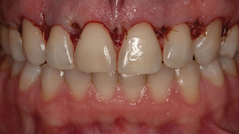
Figure 16

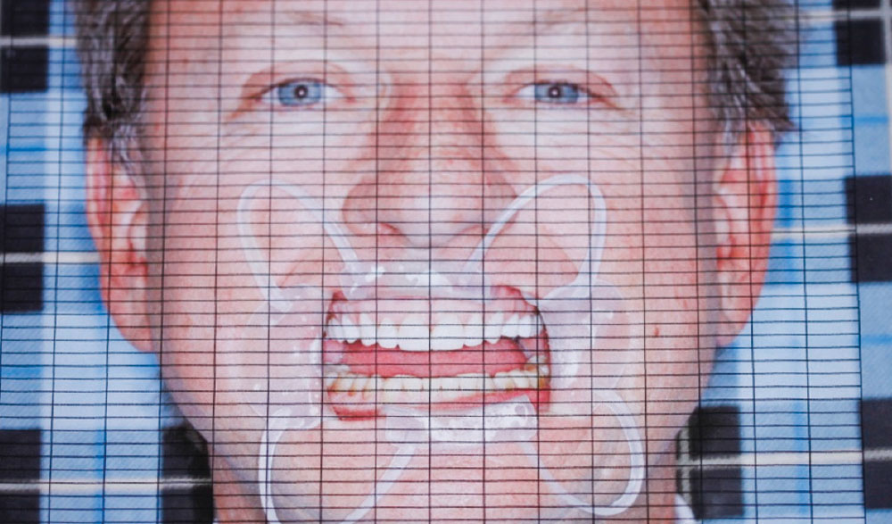
Figure 16: Using the Straight Smile Guide, decide on the correct HPC. Do this at the diagnosis and treatment planning stage, before beginning treatment. Move the guide around on the photograph to decide on the correct horizontal plane of the case. Record the anatomical points to be used for the HPC.

Figure 17

Figure 17: Provide the lab with the full-face retracted photo and the Straight Smile Guide (large one is used over the photo, small one is used for the articulator to assist in mounting and to verify accuracy). Information on the anatomical points that should be used for the correct HPC is also given to the laboratory for proper mounting. In this case, it is the gingival plane of teeth #6 & #10.

Figure 18

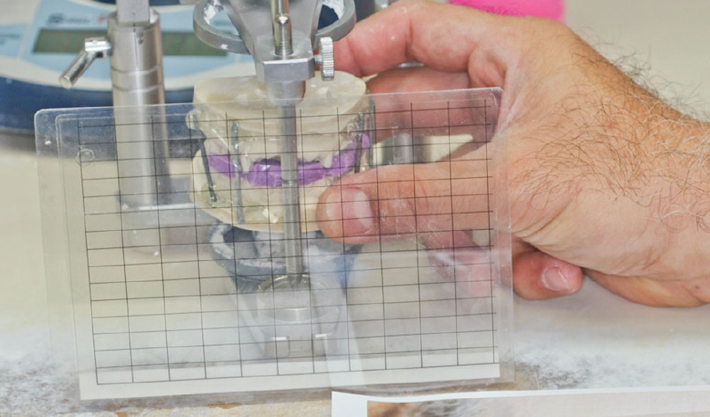
Figure 18: The lab uses the properly trimmed maxillary cast to properly mount the case. If the midline of the face is also marked on the model, the mark can be used to position the cast in the articulator just like the teeth are positioned in the mouth. Using the small Straight Smile Guide aids in proper mounting and verifies that the mounting is correct to the HPC.

Figure 19

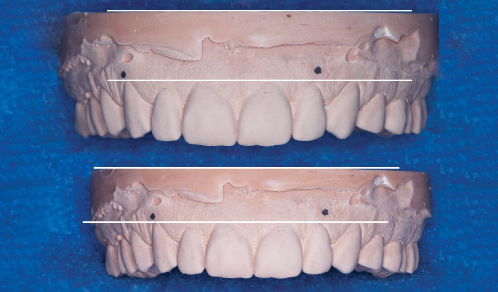
Figure 19: The lines across the top model show the base trimmed improperly — it is not parallel to the gingival plane of teeth #6 & #10, which is the chosen HPC. The lines across the bottom model show the base trimmed properly — it is parallel to the gingival plane of teeth #6 & #10, which is the chosen HPC. Mounting the base of the maxillary cast in the same horizontal plane of the articulator gives the technician making the case the correct HPC relationships (cast to articulator to patient). This minimizes the issue of uphill and downhill smiles.

Figure 20a
Figure 20b
Figure 20c
Figure 20d

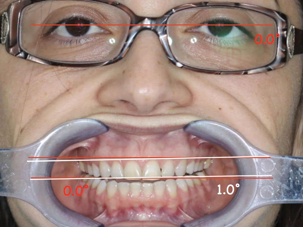
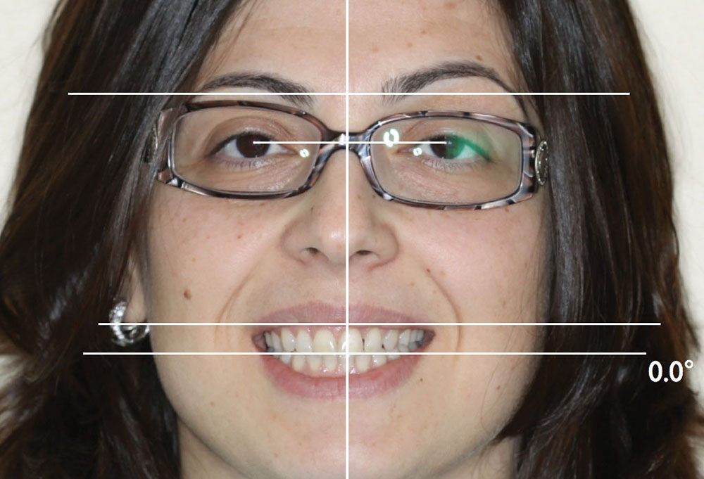
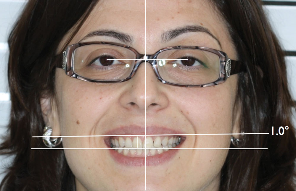
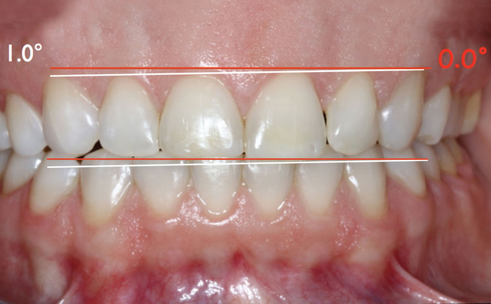
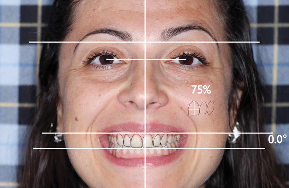
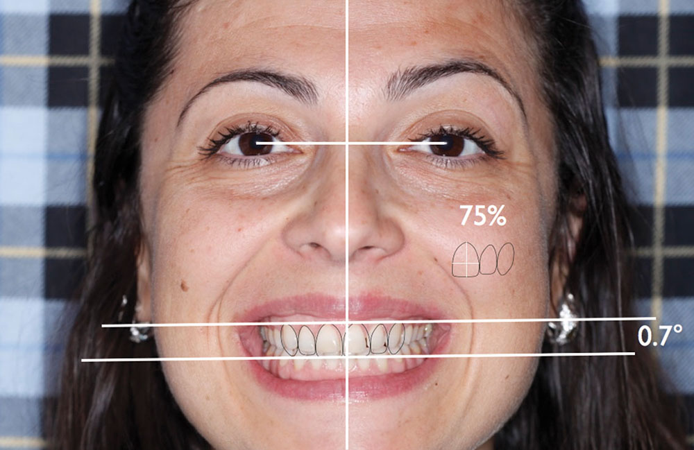
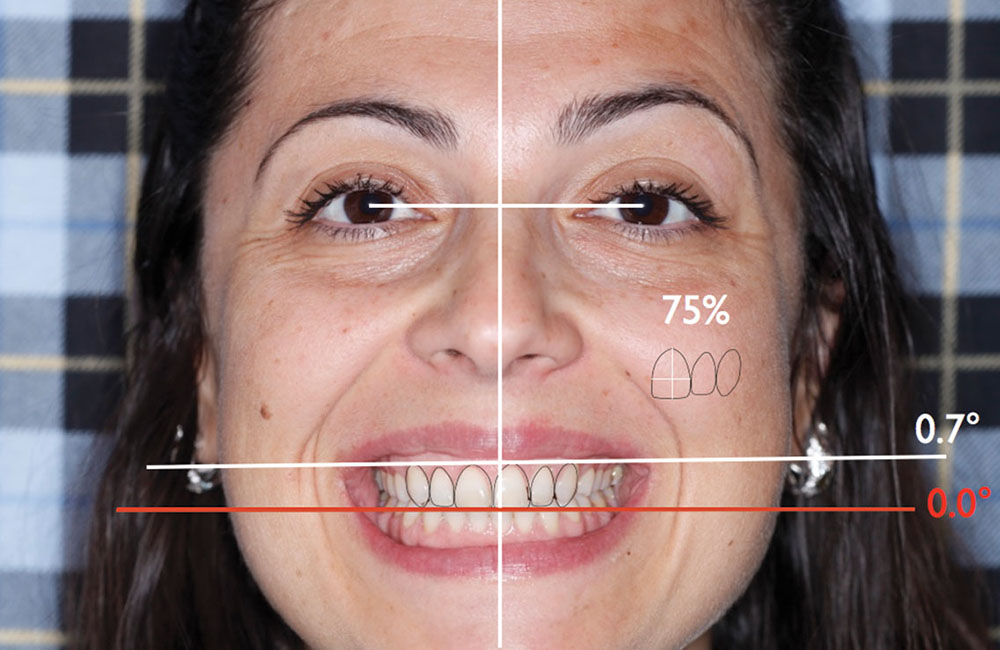
Figures 20a–20d: These four images were printed from Keynote and sent to the periodontist with an email describing the cosmetic concerns with the HPC. This was a post-orthodontic case where the roots were 50% burned off on the maxillary central and lateral incisors. In addition, there was an anterior open bite from second bicuspid to second bicuspid. Occlusion on the molars was flat due to no anterior guidance and excessive wear patterns. The case was planned to restore all of the upper and lower teeth with partial-coverage porcelain to establish appropriate occlusion on the teeth capable of carrying the load. The patient’s chief complaint was her gummy smile and lack of occlusal contact. The horizontal lines are all at 0 degrees. The lines drawn on the central represent an ideal proportion if the incisal edges were and were not lengthened. Altered passive eruption (APE) meant no supporting bone would need to be removed to treat the APE.

Figure 21

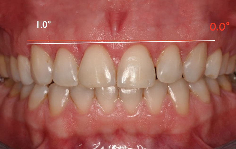
Figure 21: This photo reveals the issue with the HPC. The angulation of 1 degree should be corrected surgically before restorative care is provided. The APE on the right side requires correction, while on the left it does not. The lip asymmetry on the right displays more gingiva. In addition, the incisal plane of the cuspids parallels the gingival asymmetry; it is off by 1 degree. The simple correction for this case is to remove tissue from the right side and lengthen the incisal edges on the left to create a restorative case that is parallel to the HPC. Note that the red lines are at 0 degrees and the white lines are at 1 degree. The final gingival and incisal planes should parallel the red lines. Soft tissue and bone would need to be removed over the right bicuspids to avoid an excessive step from anterior to posterior.

Figure 22a
Figure 22b

Figures 22a, 22b: A technique that can be used to “standardize” the size of photographs is to draw a line between the spectral highlights, duplicate the line and then cut and paste it onto another photo. Resizing the second photograph until the line fits exactly in the same spots on the spectral highlights makes both photographs the same size, provided camera angle does not play a role. This enables the user to measure the length of the teeth before and after surgery to see the treatment results.

Figure 23

Figure 23: In order to have a harmonious HPC, the tissue will need to be decreased on the right and the incisal length will need to be increased on the left. Note that the 0-degree line is in red and the 1-degree line is in white.

Figure 24

Figure 24: Camera angles alter length perception, but not plane perception. This photograph was shot from too high above the teeth.

Figure 25

Figure 25: Periodontal surgery was done to “correct” the APE on the six anterior teeth and bone was removed to create a parabolic architecture. Nothing was done to parallel the gingival plane with the HPC. The right bicuspids were not touched. The gingival asymmetry was preserved rather than matching the gingival plane to the HPC. The periodontist ignored the photographs that showed exactly what was necessary to make this case a cosmetic success.

Figure 26

Figure 26: Photo at six weeks post-op. A second surgery was done at this time to remove tissue from teeth #6–9.

Figure 27

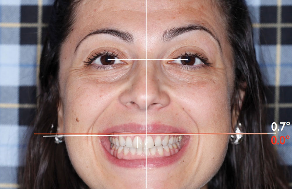
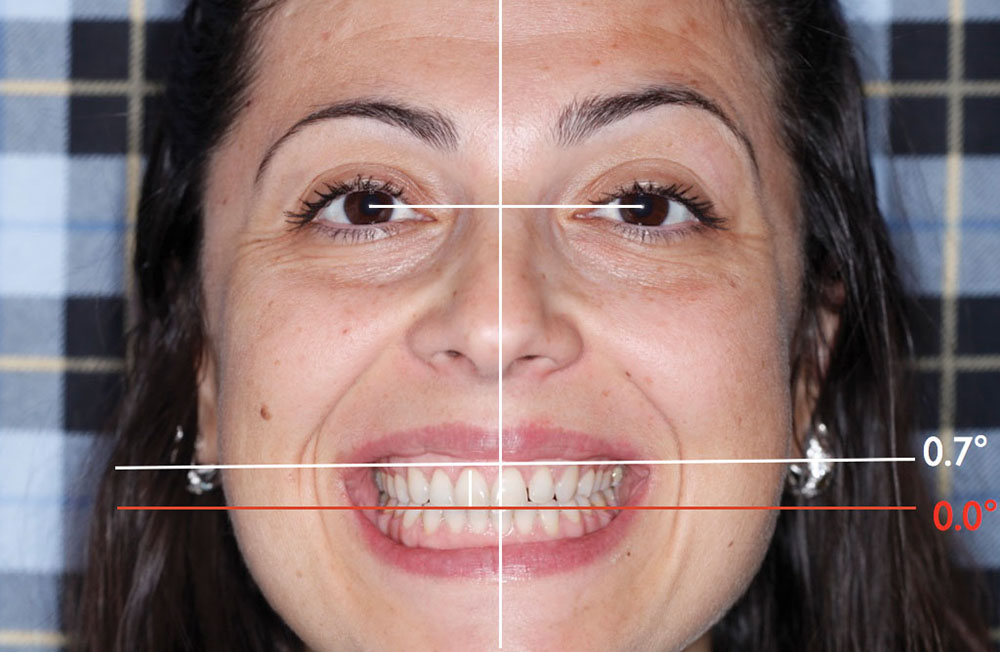
Figure 27: Even after the second surgery, the gingival plane is still 0.7 degrees off the HPC. The line drawn on tooth #8 represents the original length of the central before the two surgeries.

Figure 28

Figure 28: Cosmetic issues. Cuspid gingival plane is off 0.7 degrees. Gingival levels of the incisors are uneven or gull-winged in shape. Gingival length of #10 is longer than #7. There is a significant step between #5 & #6, and #10 & #11 should not have been lengthened. The #10 space was left too wide by the orthodontist, and the midline was not properly managed.

Figure 29a
Figure 29b
Figure 29c
Figure 29d

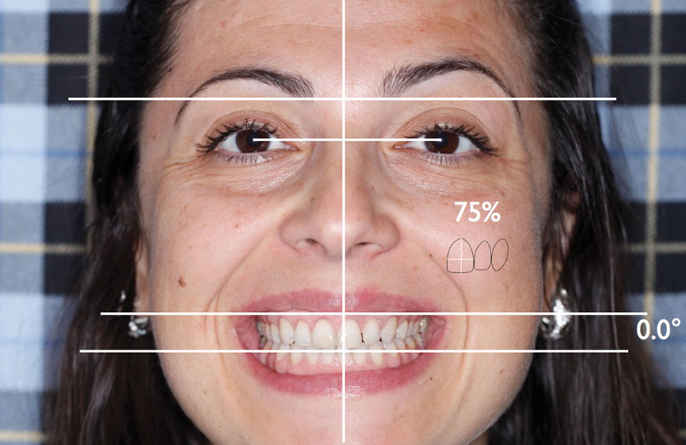
Figures 29a–29d: Outline of the teeth at 75% length and width proportion shows the ideal angle of the case relative to the HPC. Unfortunately, the gingival plane must be followed, which leaves one of two options: 1) angle the incisal edges to follow the gingival plane, thus creating a “downhill smile” that will not have the incisal edges parallel to the HPC; or 2) shorten the incisal length of the teeth on the right to make the case incisally parallel to the HPC, thus creating contralateral teeth of different lengths. Both of these options are a cosmetic compromise that could have been avoided if the periodontist had followed the restorative dentist’s request to level the gingiva with the HPC.

Figure 30

Figure 30: Another case by the same periodontist who ignored the HPC when treating the gingival plane. It is advised to use computer analysis of digital photographs to communicate important cosmetic elements to the patient, staff, specialists (periodontist, orthodontist, implantologist) and the laboratory. Use your staff to do most of the work required for the protocol.

Figure 31a
Figure 31b
Figure 31c
Figure 31d

Figures 31a–31d: This case shows a violent discrepancy between the surgical gingival line and the HPC. Fortunately, the difference in the incisal length of contralateral teeth did not compromise the case too much. The patient was thrilled. This case will be presented in its entirety in the seminar titled “Simplifying Complex Cosmetic and Restorative Dentistry,” which will be presented in Clearwater, Florida, and San Francisco, California, in early 2013.

Most of the communication needed can be transmitted with the use of a Straight Smile Guide. Created for technophobe dentists, it is a quick way to analyze and communicate critical cosmetic parameters to the team.

Dr. Bill Strupp practices in Clearwater, Florida, and lectures internationally on the subject of comprehensive cosmetic and restorative dentistry. He also publishes “Crown & Bridge UPDATE,” aimed at educating dentists in better dentistry. Contact him at 800-235-2515 or bill@strupp.com, or by visiting strupp.com.