Advanced Treatment Planning: One Recipe for Implant Success
Dental implants have become a popular treatment modality for people who have severe periodontal disease with poor prognosis of their remaining teeth. The long-term sequelae of partial and complete denture wear have been elucidated in the literature. The following is a case history of a patient who required full-mouth implant rehabilitation. There are several unique features of this case, including a treatment planning perspective that may help others plan comprehensive care for their patients in a more holistic fashion.
CASE REPORT
Diagnosis
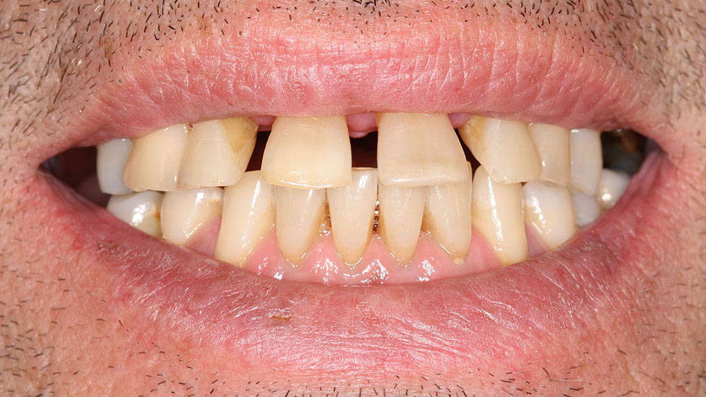
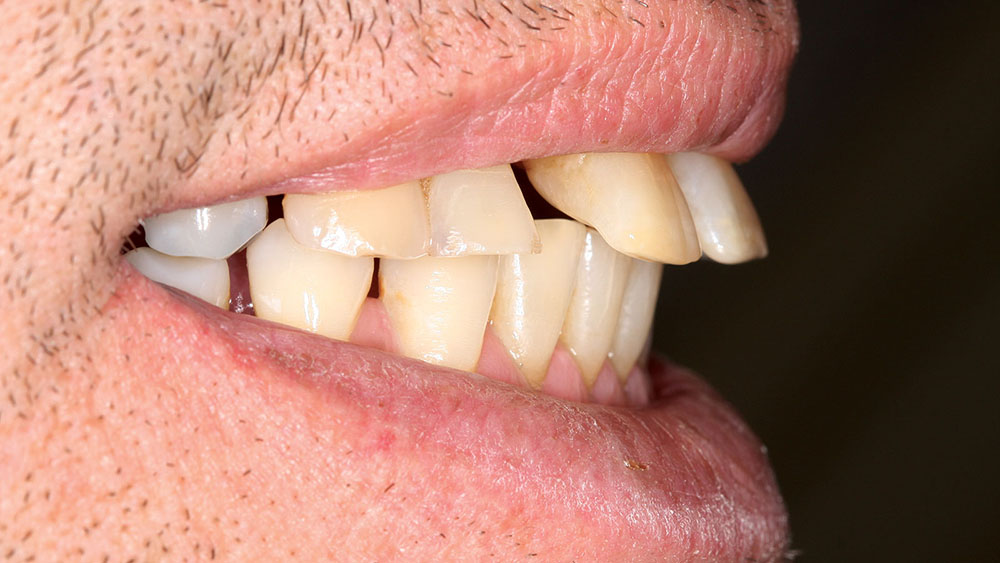
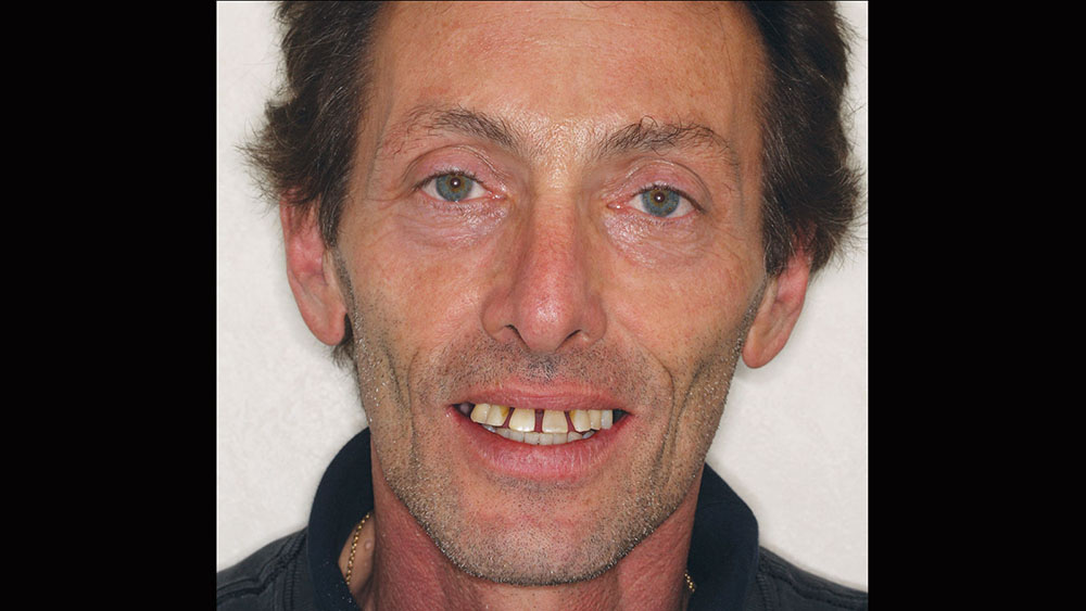
A 56-year-old white male presented with a history of severe type IV advanced periodontitis. He was a chronic pack-a-day smoker. When asked what brought him to the dentist for treatment, his response was: "I was at a family function, and when I saw the photos, I realized that I was self-consciously keeping my lips closed for all photos! I realized then and there that I couldn’t smile, and it was really upsetting me … affecting me emotionally." He was ashamed of his smile and knew it was affecting all aspects of his life. He was also concerned about his splayed anterior teeth and how the spaces were getting bigger. Lastly, he was straining to close his lips and had excess mandibular gingival display upon smiling (Figs. 1, 2).
Treatment Planning: Listening — The Lost Art!
The treatment planning visit began with a discussion of the patient’s concerns, desires and budget. The types of prostheses available to solve the patient’s problems were discussed in a fashion that allowed him to choose removable or fixed dentistry, as well as an upgrade path that could transition from one to the other based upon budgetary constraints.
After a candid discussion of the costs, alternatives, advantages, disadvantages, benefits and risks of each treatment option, the patient decided upon a full-mouth rehabilitation with fixed bridgework supported fully by endosseous implants (BioHorizons; Birmingham, Ala.). The cost of comprehensive treatment can be a bigger obstacle for the dentist than the patient. Oftentimes, dentists prejudge patients and their budgets, precluding them from selecting the treatment option that will benefit them the most. While lecturing, the author often makes the rhetorical remark, "Do we treatment-plan what we do well, or what will do well, for our patients?" This is meant to challenge us to comprehensively diagnose treatment for our patients, even if it means that the patient is referred out to a colleague who may be more experienced in a particular type of treatment. It is very educational to participate with a mentor, or to observe treatment in complex cases when referrals are made.
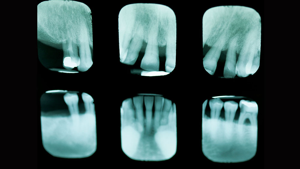
At the treatment planning appointment, a panoramic radiograph and full-mouth radiographs were taken (Fig. 3). Next, to help us visualize the desired cosmetic outcome, photographs were taken and sent away for cosmetic imaging. Alginate impressions, bite registrations with and without a "stick bite" (a stick placed into the bite registration material and parallel to the interpupillary line), and a face-bow transfer were used to facilitate mounting the case accurately on a semi-adjustable articulator. Vinyl polysiloxane (Aquasil Ultra [DENTSPLY Caulk; Milford, Del.]) impressions were taken, allowing for multiple pours and to serve as a long-term record of his preoperative condition.
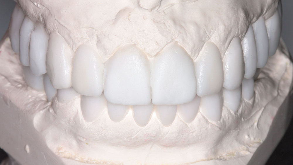
The casts would also be sent to the technicians at BDL Prosthetics for a diagnostic wax-up. Details regarding the case were shared with the team manager so that all cosmetic issues could be addressed before fabricating the barium sulfate stents and sending the patient for a CAT scan. At this visit, the desired shade was also discussed. The prescription requested that the mandibular anteriors be intruded and lingualized. Then, the maxillary teeth could be moved lingually to match the idealized mandibular setup. The shape of the teeth was changed from tapering to square tapering in order to broaden the gingival contours of the teeth and to increase the smile display. Next, the laboratory technician was instructed to labialize the buccal posterior segments to increase the cosmetics and smile display of the buccal corridors. Lastly, the vertical dimension of occlusion (VDO) was decreased to improve lip patency and to make it easier for the patient’s lips to touch at rest. The dental laboratory team was asked to photograph the wax-up to show me if our goals were attained, before sending the wax-up back. Upon receiving the wax-up back in my office, I examined it and made some further changes so that the master diagnostic wax-ups would be a blueprint for the desired cosmetic outcome. These alterations included changing the buccal overjet and overbite, as well as minor tooth reshaping (Fig. 4). The dental laboratory team was then instructed to make dentures and prefabricated temporaries (BioTemps® Provisionals [Glidewell Laboratories; Newport Beach, Calif.]) so that two different types of provisionals would be available at the time of surgery.
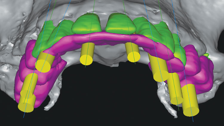
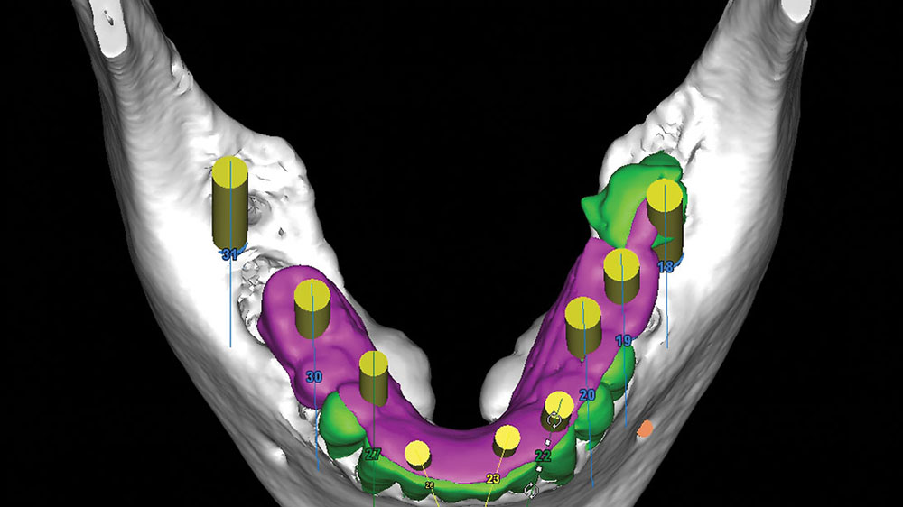
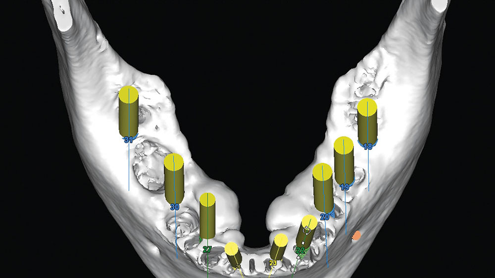
This next step in the process of proper treatment planning is of vital importance. With help from 3DDX Treatment Plan (3D Diagnostix; Brighton, Mass.), the CAT scan was converted, allowing placement of the implants via SimPlant® software (Materialise Dental; Waltham, Mass.). The use of 3DDX’s deluxe software allows each layer of information to be seen in different colors. The wax-up can be placed in one color, the teeth in a second color and the implants in a third color so that all aspects of implant placement can be analyzed (Figs. 5a, 5b).
The adjusted image with implants placed and the barium sulfate stent of desired tooth positions could be used to plan the surgical sequence and parameters of implant placement. Measurements could be made from existing tooth positions for initial osteotomies, and measurements from these placed implants could be used for measurements for the second-stage surgery. The use of a surgical guide made from the diagnostic wax-up, but transferred to existing teeth, allowed the implants to be placed within the confines of the desired tooth locations. This was done without the need for guide tubes in the surgical guide. Utilizing the deluxe tools allowed for removal of two masks, so evaluation of the underlying bone could be performed as well (Fig. 6).
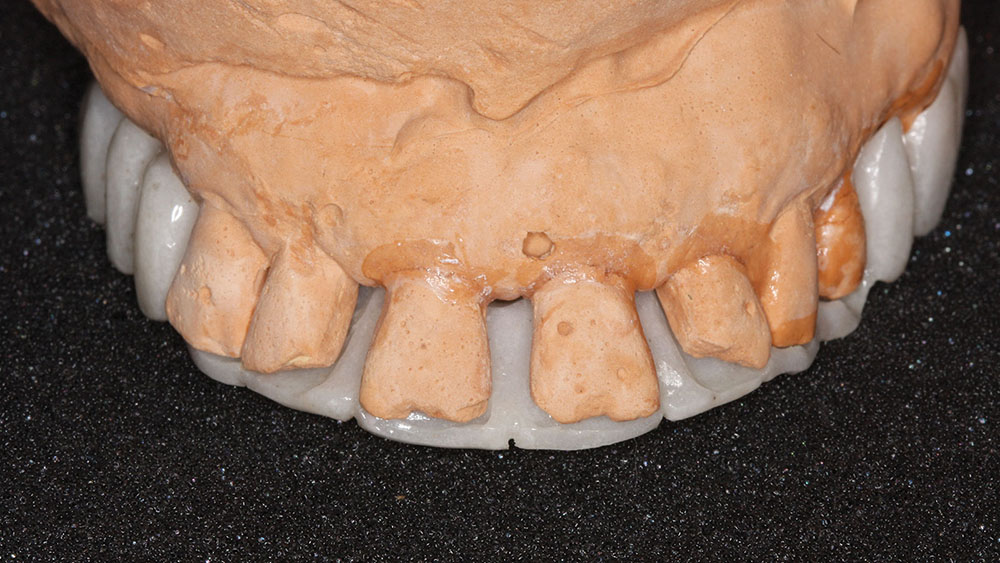
After the diagnostic wax-up was completed, the laboratory team was instructed to make a barium sulfate stent by transferring the data from the diagnostic wax-up (molars, bicuspids and lingual of maxillary anteriors only) to the existing anterior teeth as seen in Figure 7. This barium sulfate stent was returned to our office for evaluation and verification on the models.
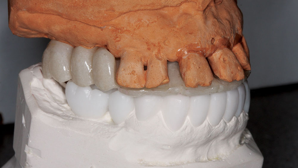
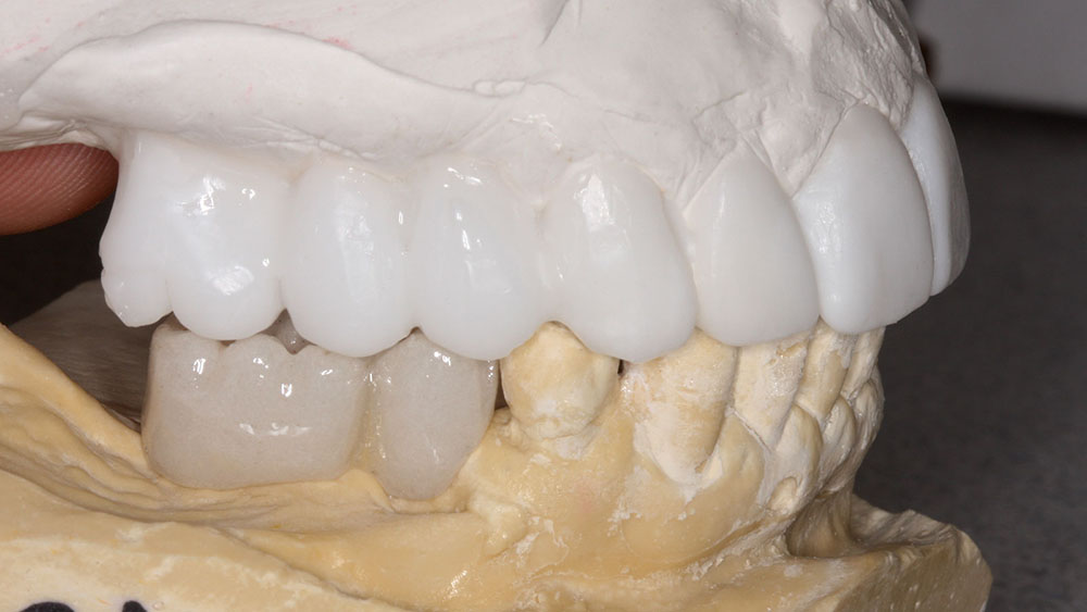
The maxillary surgical guide was cross-mounted to the mandibular diagnostic wax-up to verify that the VDO was maintained (Fig. 8). Then, the maxillary diagnostic wax-up was cross-mounted to the mandibular surgical guide to verify that all changes were made and were consistent with the proposed tooth positions (Fig. 9). The intaglio of the maxillary surgical stent had pilot osteotomy holes placed based upon the desired implant positions and would be used for both phase one and phase two maxillary surgeries.
Converting the barium sulfate stent to a surgical guide by drilling pilot holes at the desired implant positions could now allow for prosthetically driven implant surgery (Fig. 10). While a CAT-scan-generated surgical guide could have been created that was either tooth-borne or bone-braced with stabilizing pins, the methodology utilized allowed for some surgical freedom at the time of surgery. If a surgical site had poor bone quality or anatomy, the surgical guide that was fabricated would allow the osteotomy to be moved several millimeters in either direction and still remain within the contours of the future crowns as designed in the original wax-up.
Sequencing: Maxillary Surgery
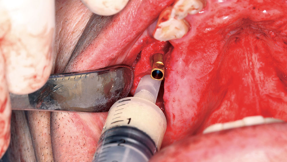
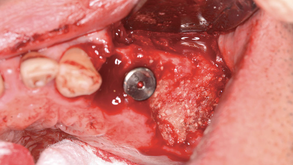
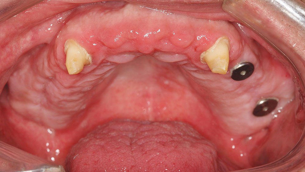
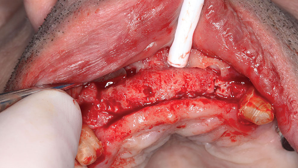
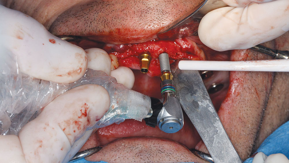
The patient preferred a fixed maxillary provisional, so the posterior maxillary surgery was performed first. The posterior teeth were removed, and four implants were placed with grafting of all defects and extraction sites (Figs. 11, 12). At the same visit, the anterior teeth were removed, and socket preservation was performed with DynaBlast® putty (Keystone Dental; Burlington, Mass.) and Epi-Guide® membranes (Kensey Nash; Exton, Pa.). The placement of posterior implants was possible due to the amount of residual bone in the desired implant positions. The canines were used to retain the maxillary BioTemps, which were trimmed to include only first bicuspid to first bicuspid occlusion (Figs. 13a, 13b). This would satisfy the patient’s esthetic concerns without producing a significant cantilever in the provisional. Upon reentry, the bone was successfully regenerated and had good dimension and density prior to placement of the BioHorizons implants (Figs. 14a, 14b).
BioHorizons implants were selected for this case due to the increased bone-to-implant contact made possible by the parallel design and reverse buttress threads. This was an important factor, given the poor bone quality (D4), which was assessed by evaluating the Hounsfield units on the CAT scan prior to the first surgery.
The canines were then extracted, and, due to their position, immediate implants were placed (Fig. 15). DynaBlast paste was used to fill the gap that existed between the implant and the buccal plate of bone. After six months of healing, the posterior implants could receive PEEK (BioHorizons) temporary abutments, and two IMTEC (3M™ ESPE™; St. Paul, Minn.) mini implants could be placed in sites #7 and #10 to give support to the maxillary provisional (Fig. 16).
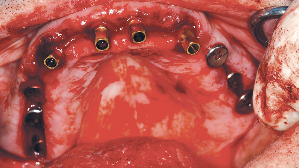
The reason the anterior implants were delayed and grafting was performed instead of immediate implant placement was due to the significant difference between where the existing teeth were and where the proposed implants were to be placed. Because the existing cortical bone in the sockets would push the osteotomy bur labially, the decision to place the implants into their more lingual position could be accomplished more predictably after the bone in the sockets had regenerated. The maxillary implants were allowed to integrate for six months, and they were uncovered so that permucosal extensions (BioHorizons) could be placed and help to develop adequate soft-tissue contours.
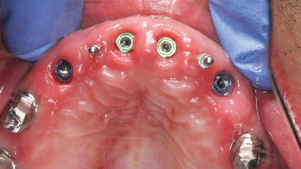
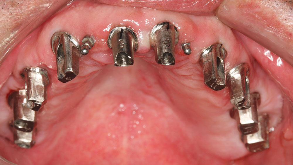
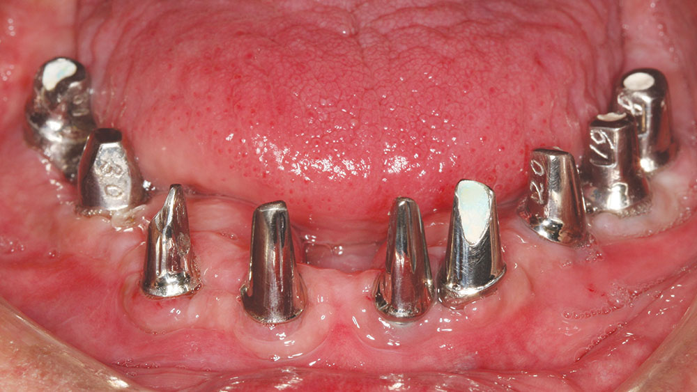
Then the 3inOne™ Abutments (BioHorizons) with ball-top screws were placed and verified radiographically prior to making a master impression with Aquasil Ultra and B4® Surface Optimizer wetting agent (DENTSPLY Caulk) (Fig. 17).
Sequencing: Mandibular Surgery
After the first maxillary surgery, the lower surgery was done in one surgical visit. The patient had prominent lingual tori, and the option was given to the patient to remove them. The patient had no discomfort or problem with the tori, so they were left. The edentulation of the mandibular teeth and implant placement were accomplished based upon the CAT-scan-generated surgical guide. The mandibular surgical guide was placed intraorally to ensure that the maxillary provisional would line up with the lower guide, which was based upon the diagnostic wax-up (Fig. 18).
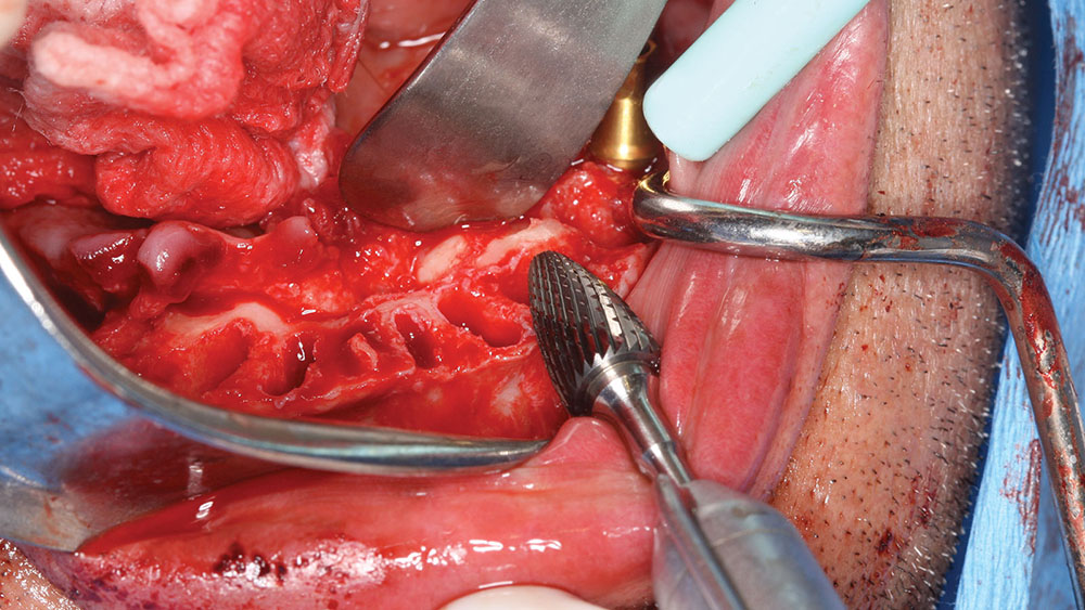
The amount of leveling of the mandibular ridge was preplanned with the SimPlant software and performed with a bone-trimming bur (Fig. 19). At the time of surgery, the implants were placed within the sockets according to the projected new tooth positions.
The mandibular tori were used to retain a lower denture, which had been lined with HydroCast® (Sultan Healthcare; Hackensack, N.J.) tissue conditioner. The soft liner was backed up with acrylic to form a firm, yet thin, flange for the denture, and the patient had excellent retention and required no adhesive for the mandibular denture. The lower implants were placed and permucosal healing abutments were placed (healing caps) to eliminate a secondary surgery for uncovery at a later date.
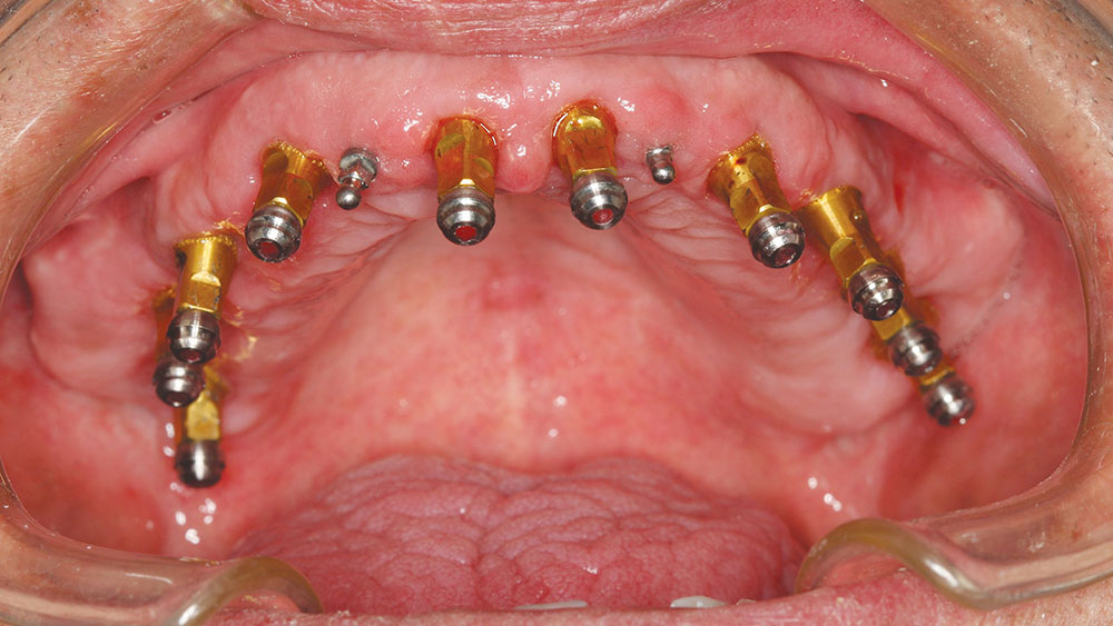
A six-month healing period took place prior to full-mouth impressions. The 19 implants were impressioned using the 3inOne Abutment with ball-top screws (BioHorizons). The provisonals had allowed the vertical dimension to be maintained throughout treatment, and the use of sectioned provisonals allowed a bite registration to be accomplished at this impressioning appointment. A small section of the provisionals was left in the mouth on the upper and lower right side to take a bite registration. Then, the rest of the provisionals were placed, the initial temporaries were removed and a second bite was taken, allowing the laboratory team to cross-mount the casts.
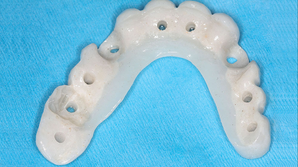
Delivery of the custom cast abutments was performed at the next visit (Figs. 20a, 20b). Seating jigs were fabricated, and all abutments were radiographed to verify complete seating. Next, these were torqued to 30 Ncm, and the new maxillary and mandibular provisionals were delivered. After adequate healing, the connective tissue was firm and stippled.
It should be noted that these provisionals were made at a different dental laboratory and did not match the original provisionals. As a result, the patient’s VDO was open, and the provisionals required extensive adjustment to bring the patient back to the point where lip seal at rest could be accomplished. It would have been prudent to send these provisionals back for refabrication at this point, and then the case could have been completed several months earlier. It only takes one miscommunication to delay a case, and because the abutments were already delivered and seating was verified, these provisionals needed to be used in order to not have to remove the abutments. So, even though the provisionals were usable, they required extensive adjustment to bring them back to the proper vertical and cosmetic appearance that had been previously approved by the patient in the first provisionals.
After bisque-bake try-ins, some occlusion-related issues remained that required additional try-in visits, as well as equilibration by the dental laboratory team. It is imperative that excursive interferences and protrusive contacts be evaluated prior to finalization of the porcelain to avoid lengthy intraoral adjustments/polishing at final cementation.
Final Cementation Appointment
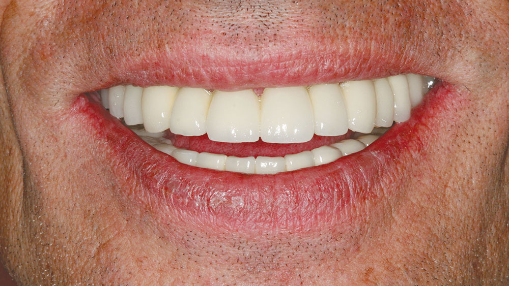
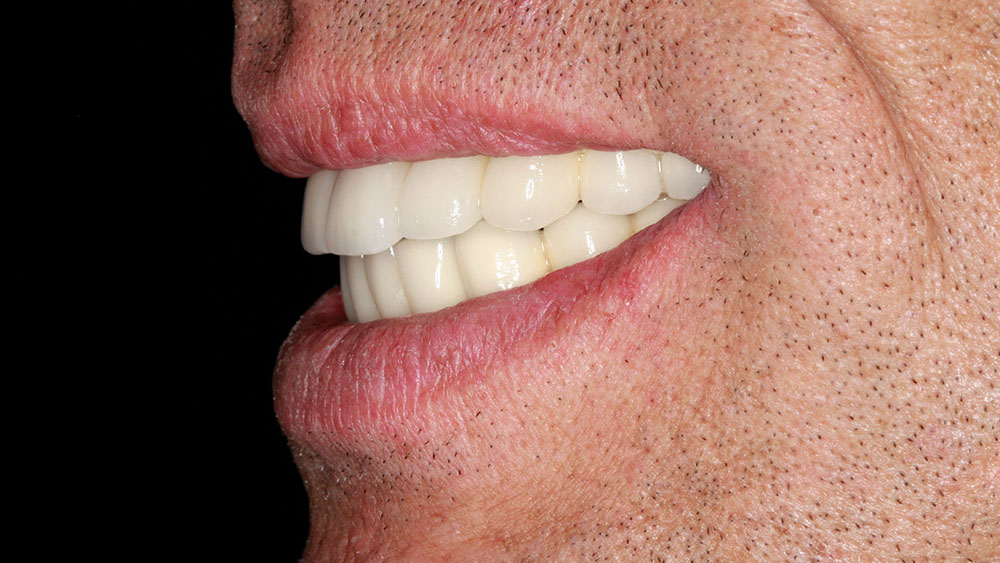
The abutments were retorqued, and periapical radiographs were taken of each implant to verify abutment and prosthesis seating. The access openings in the implants were filled with cotton and TempoSIL® 2 (Coltène/Whaledent; Cuyahoga Falls, Ohio), and the prostheses were cemented with a retrievable implant cement (Retrieve™ [Parkell, Inc.; Edgewood, N.Y.]) (Figs. 21a, 21b). The desire to cement these prostheses with permanent cement needed to be balanced with the stress of removing these at a later date in the event of a failure. The patient understood that should a prosthesis loosen with time, more rigid cement could be used in the future. The cement chosen has an inherent flexibility that is weaker in shear, and with proper crown removal instruments, should flex slightly and allow for prosthesis removal in the future.
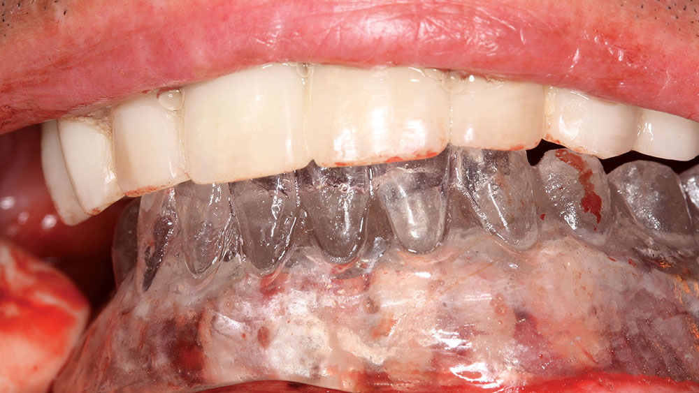
The occlusion was checked for interferences, and a balanced occlusal construct was present. The patient was given an immediate nightguard, which was fabricated chairside with the use of iNterra™ (DENTSPLY Caulk) material and the iNterra oven (DENTSPLY Prosthetics; York, Pa.) that would cure this material in 10 minutes. Later, a Talon® Splint (Space Maintainers; Calgary, Alberta) was fabricated, which would allow a soft intaglio (when placed in hot water) and hard occlusal shell to be placed on the upper prosthesis, creating a “shock absorber” to prevent increased force factors from nighttime bruxism.
CLOSING COMMENTS
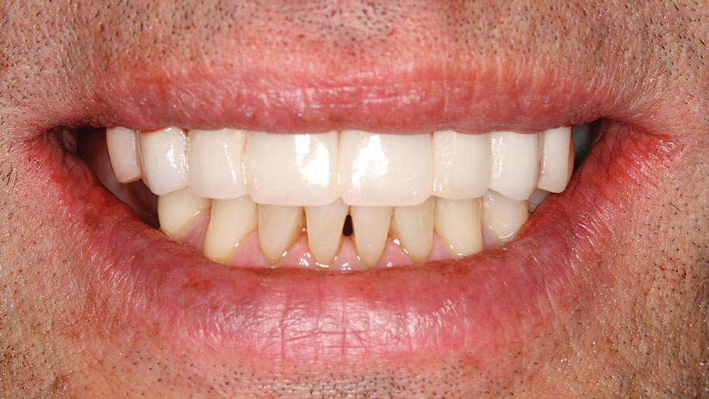
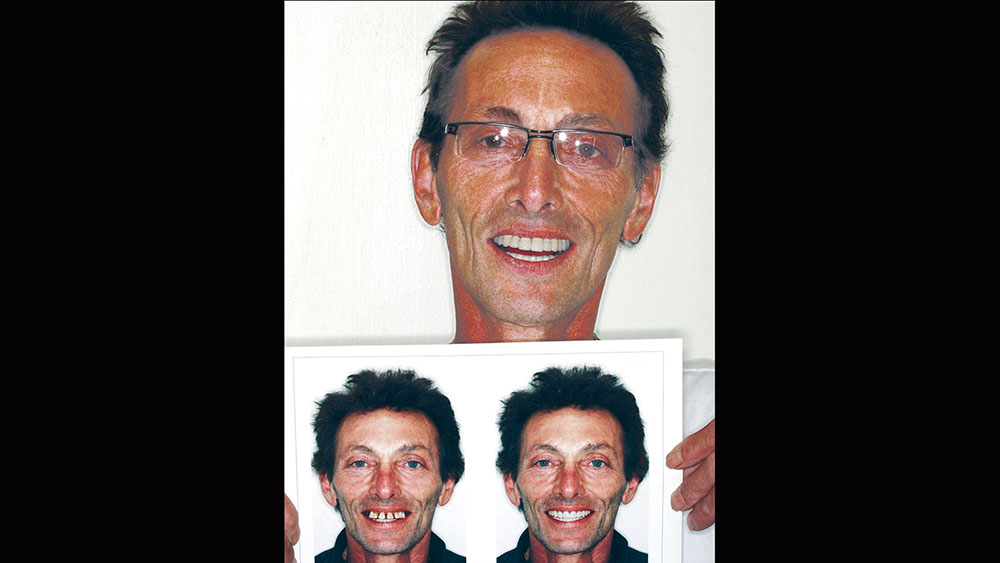
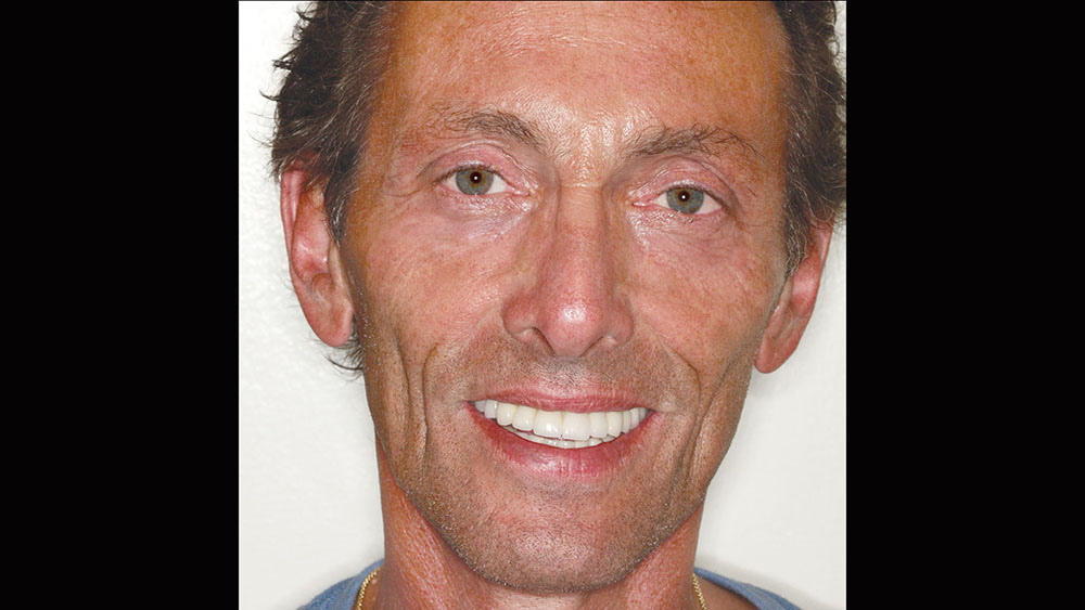
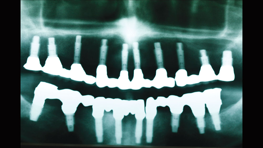
Treatment planning is an art and is as complex as the patients we serve. Utilizing the upgradeable dentistry dialogues that the author lectures about can help patients choose the level of dentistry that will provide them with a dental outcome that is appropriate for their emotional, psychological and financial situation. In this case, the final esthetic outcome closely matched the preoperative cosmetic simulation (Fig. 22). The pre- and postoperative photos show the desired occlusal construct. The decrease in horizontal overjet, the improvement of lip patency, and the improved smile display are all a careful product of dentist-laboratory, team-patient communication throughout treatment (Figs. 23, 24). The final panoramic radiograph demonstrates the optimal A-P spread and parallelism. In addition, it shows that the bridges were broken up to provide stress-breaking relief at the mental foramen (Fig. 25).
The case presented herein illustrates the value of structuring a treatment plan by utilizing patient-driven, facially generated esthetics and prosthetically driven implant placement.
ACKNOWLEDGMENT
Dr. Winter would like to thank Glidewell Dental Laboratories for the materials used in this article. Disclaimer: Dr. Winter received some material support from Glidewell Dental Laboratories.
Dr. Winter is a master in the AGD and a diplomate in the International Congress of Oral Implantologists. He holds fellowships in the Academy of Dentistry International and the International College of Dentists. He graduated from the University of Minnesota School of Dentistry in 1988. Dr. Winter has published numerous articles on implant and reconstructive dentistry emphasizing "Upgradeable Dentistry" and "General Dentistry As a Specialty." He can be reached at rick@winterdental.com.
Disclosure: Dr. Winter reports no disclosures.
SUGGESTED READINGS
- Boggan RS, Strong JT, Misch CE, Bidez MW. Influence of hex geometry and prosthetic table width on static and fatigue strength of dental implants. J Prosthet Dent. 1999 Oct;82(4):436-40.
- Buser D, Halbritter S, Hart C, et al. Early implant placement with simultaneous guided bone regeneration following single-tooth extraction in the esthetic zone: 12-month results of a prospective study with 20 consecutive patients. J Periodontol. 2009 Jan;80(1):152-62.
- John V, De Poi R, Blanchard S. Socket preservation as a precursor of future implant placement: review of the literature and case reports. Compend Contin Educ Dent. 2007 Dec;28(12):646-53.
- Chee WW, Donovan T. Use of provisional restorations to enhance soft-tissue contours for implant restorations. Compend Contin Educ Dent. 1998 May;19(5):481-9.
- Tarnow DP, Cho SC, Wallace SS. The effect of interimplant distance on the height of inter-implant bone crest. J Periodontol. 2000 Apr;71(4):546-9.
- Rosenfeld AL, Mandelaris GA, Tardieu PB. Prosthetically directed implant placement using computer software to ensure precise placement and predictable prosthetic outcomes. Part 1: diagnostics, imaging, and collaborative accountability. Int J Periodontics Restorative Dent. 2006 Jun;26(3):215-21.
- Malchiodi L, Ghensi P, Cucchi A, et al. A comparative retrospective study of immediately loaded implants in postextraction sites versus healed sites: results after 6 to 7 years in the maxilla. Int J Oral Maxillofac Implants. 2011;26(2):373-84.
- Weinberg LA. CT scan as a radiologic data base for optimum implant orientation. J Prosthet Dent. 1993 Apr;69(4):381-5.
- Amet EM, Ganz SD. Implant treatment planning using a patient acceptance prosthesis, radiographic record base, and surgical template. Part 1: Presurgical phase. Implant Dent. 1997 Fall;6(3):193-7.
- Daftary F, Bahat O. Prosthetically formulated natural aesthetics in implant prostheses. Pract Periodontics Aesthet Dent. 1994 Nov-Dec;6(9):75-83.
- Stellino G, Morgano SM, Imbelloni A. A dual-purpose, implant stent made from a provisional fixed partial denture. J Prosthet Dent. 1995 Aug;74(2):212-4.
- Amet EM, Phinney TL. Fixed provisional restorations for extended prosthodontic treatment. J Oral Implantol. 1995;21(3):201-6.
Reprinted by permission of Dentistry Today, ©2012 Dentistry Today.

