Freehand Placement of Dental Implants: A Recipe for Success (1 CEU)

June 20, 2025
Timothy F. Kosinski, DDS, MAGD image
Timothy F. Kosinski, DDS, MAGD
Jacqui Kozlowski, image
Jacqui Kozlowski

Dental implantology is a predictably successful treatment when the established principles are followed. Similar to a chef following a recipe, deviations from this methodology can result in lower success rates and suboptimal outcomes. In this case report, we will illustrate a set of rules and principles that together constitute a recipe for success with dental implants.

Basic Rules to Remember

  • There must be at least 3 mm between adjacent implants to allow for blood supply and room for prosthetic components.
  • The implant body must be positioned at least 2 mm from the periodontal ligaments of adjacent teeth.
  • There must be a minimum of 1 mm of bone facial and lingual to the implant.
  • There must be a band of attached gingiva of at least 2 mm on the facial aspect of the implant.
  • The width of the implant should be one-half the mesial-distal dimension of the tooth being replaced. 
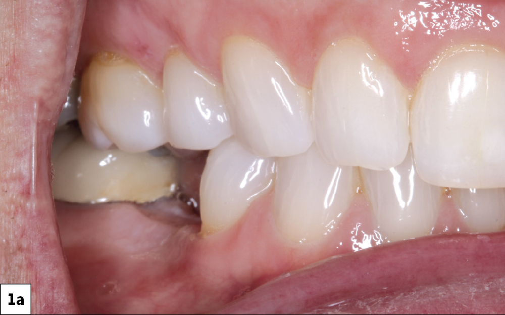
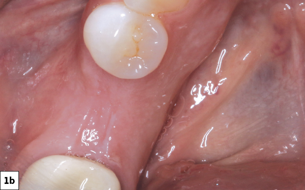
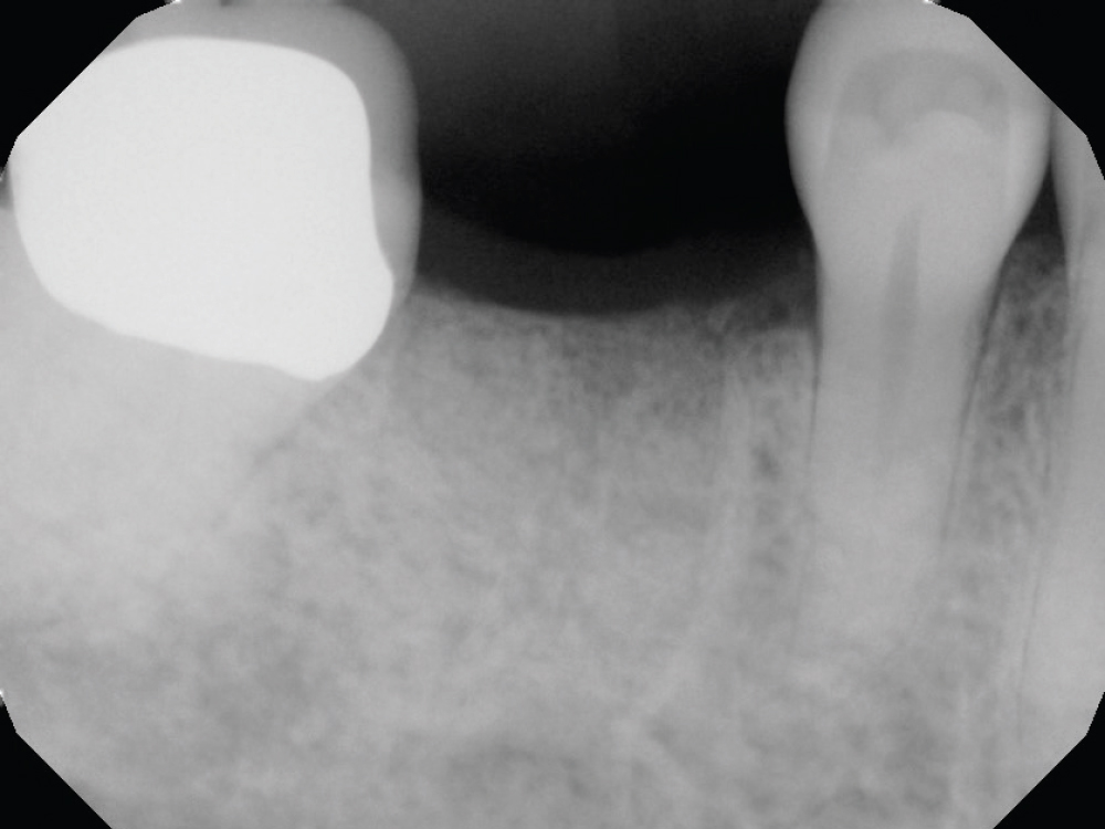
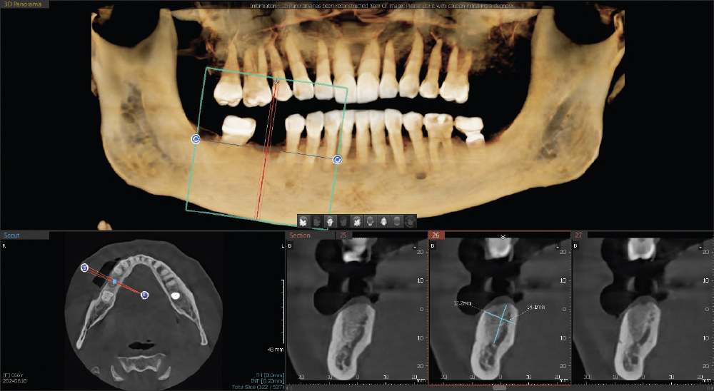
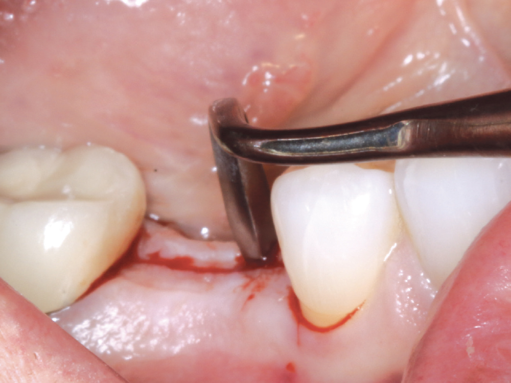
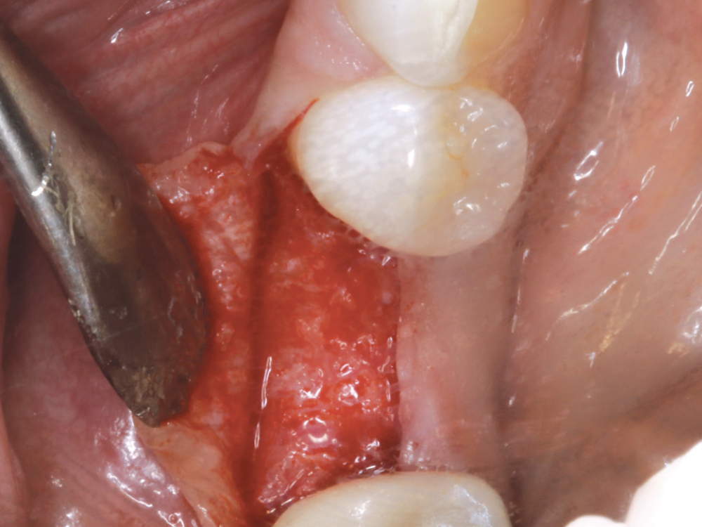
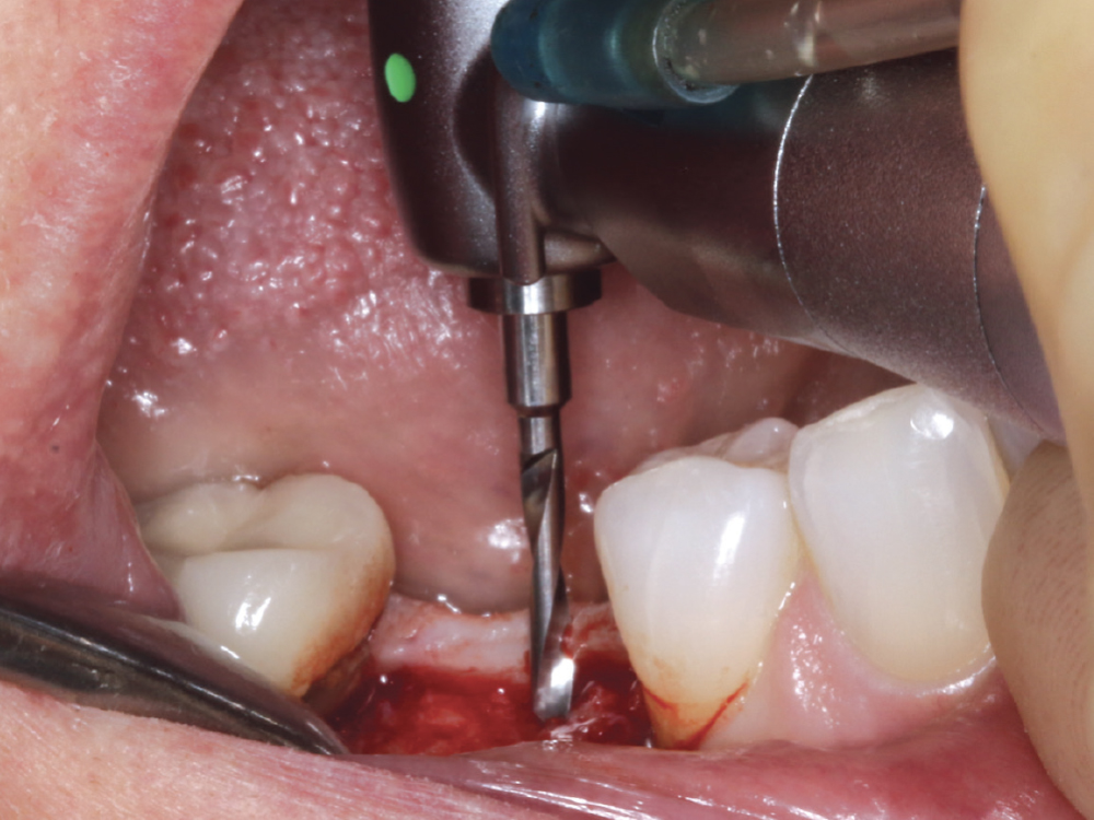
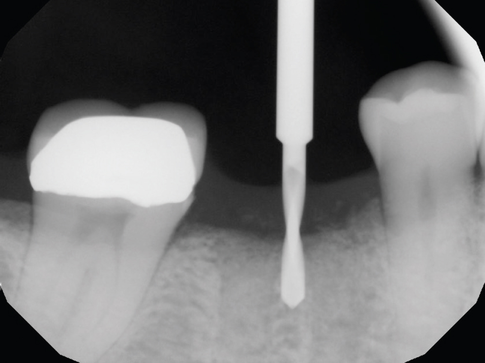
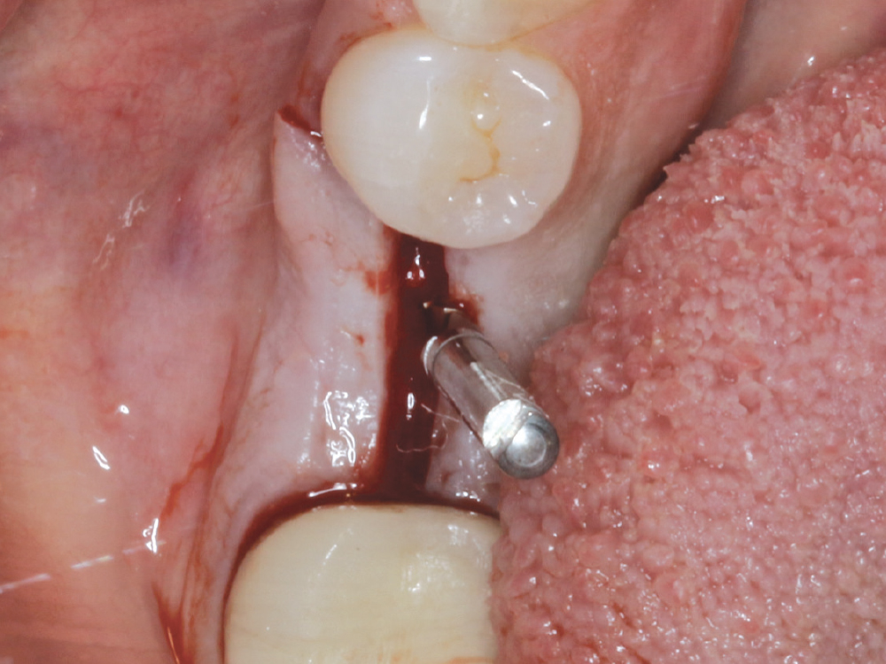
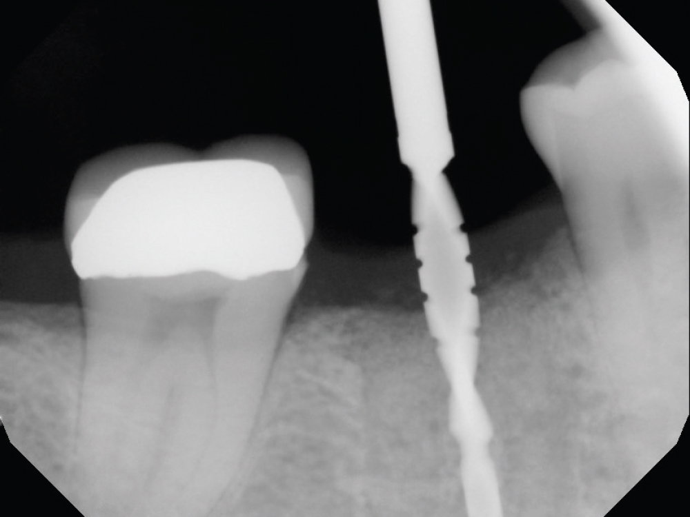
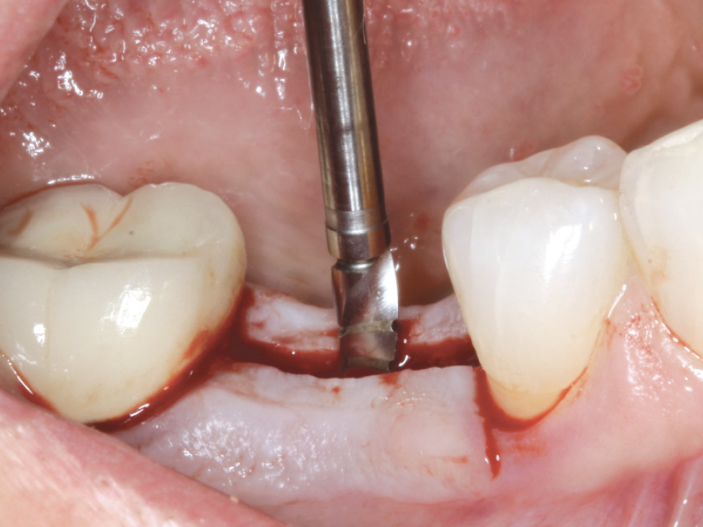
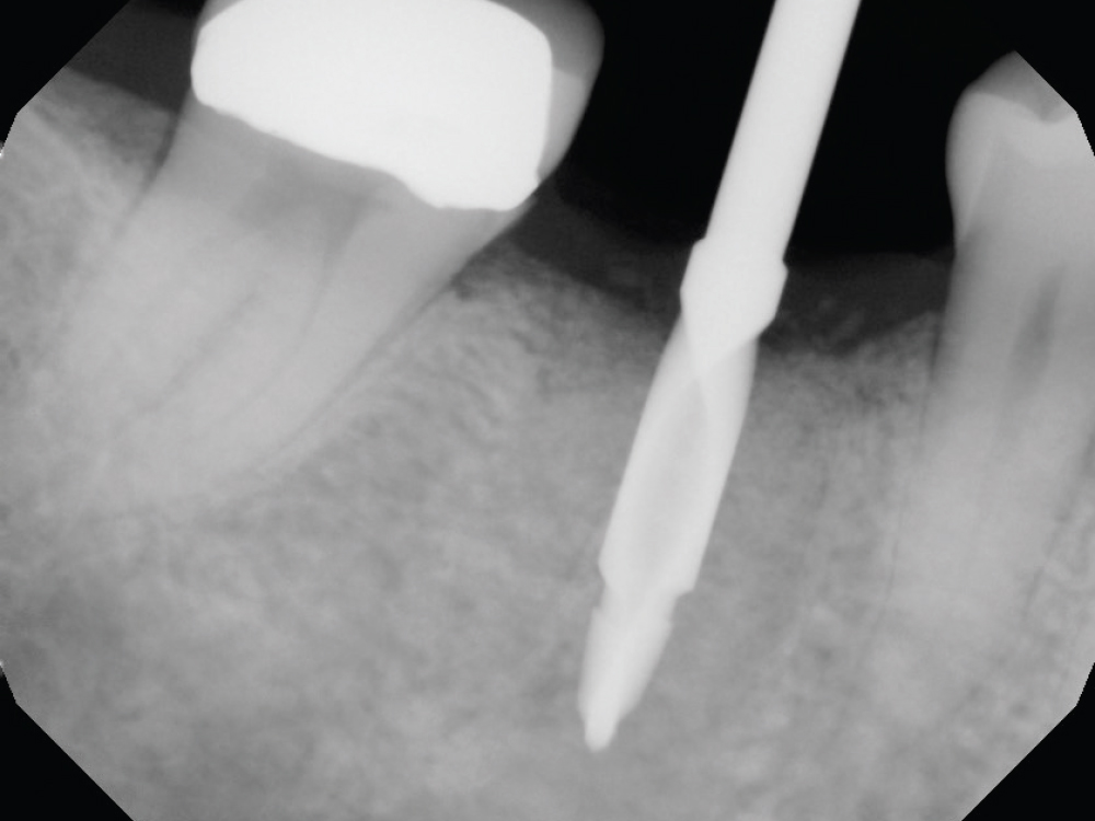
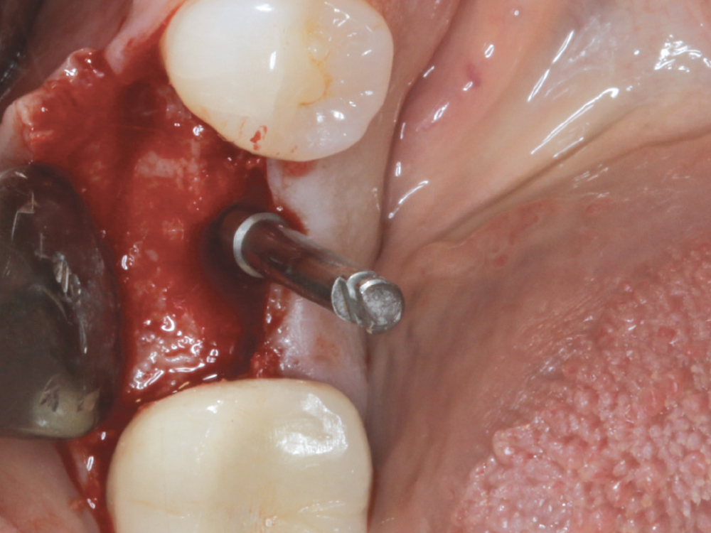
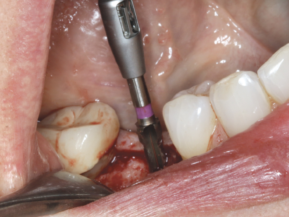
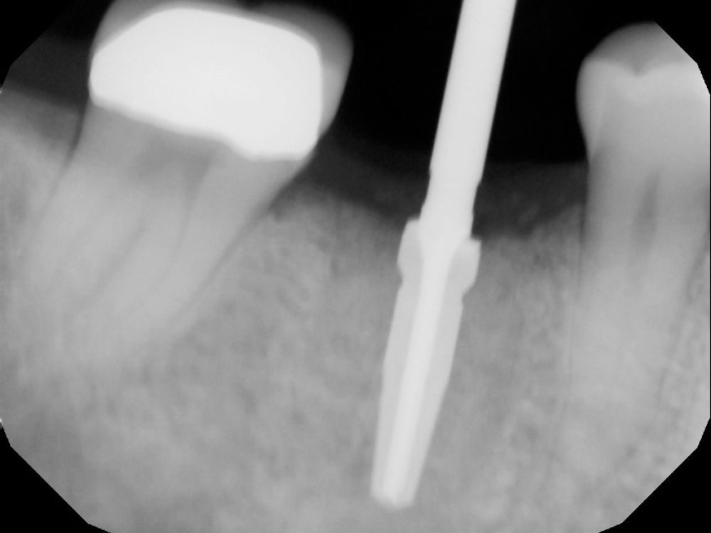
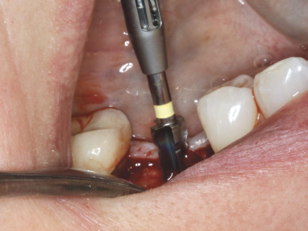
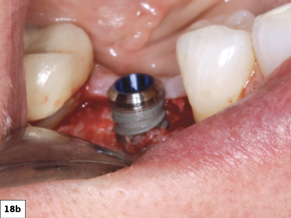
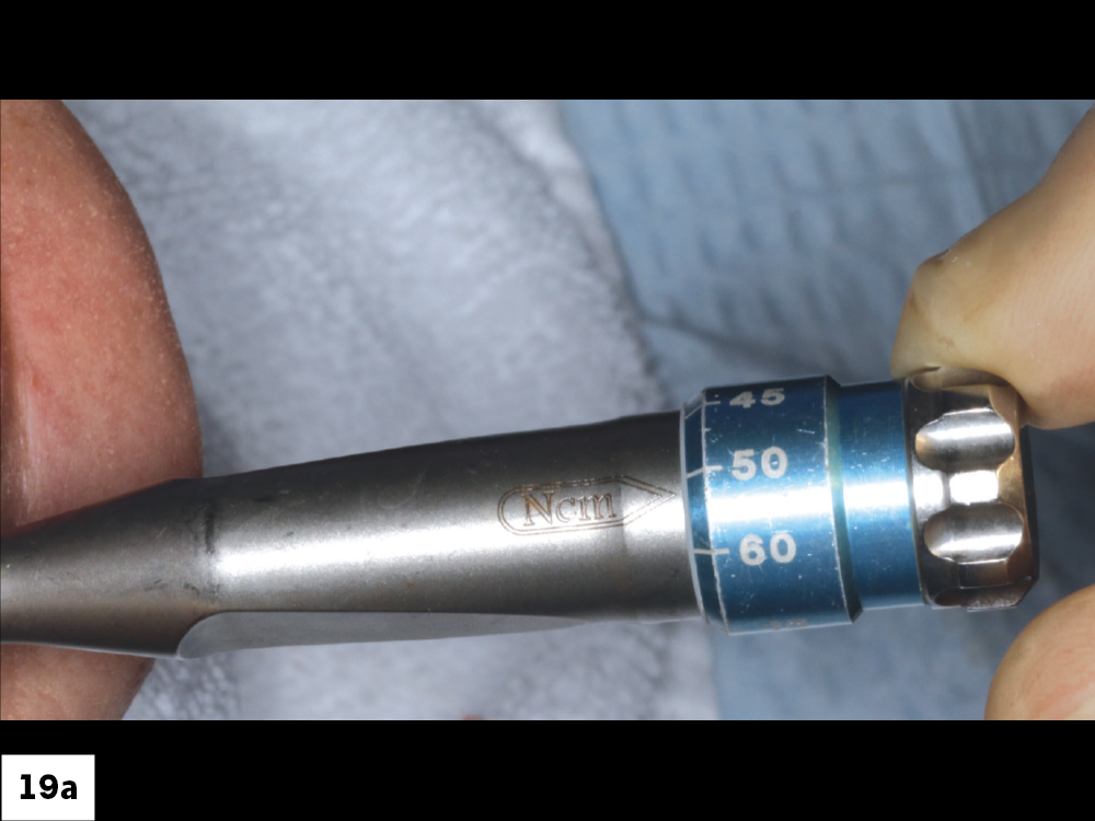
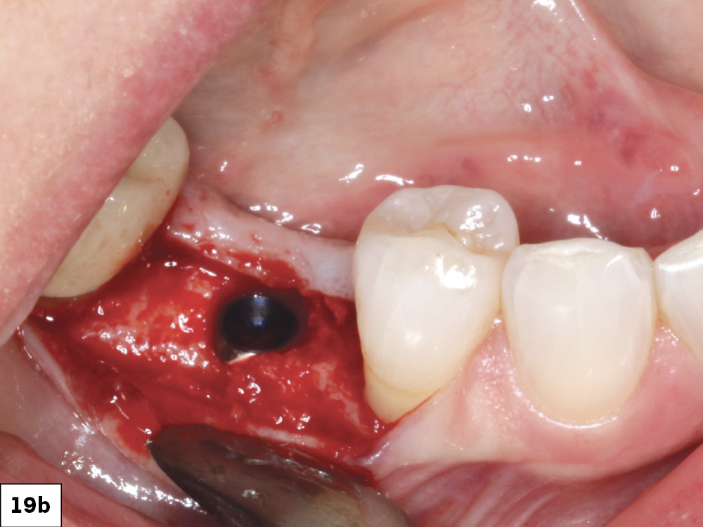
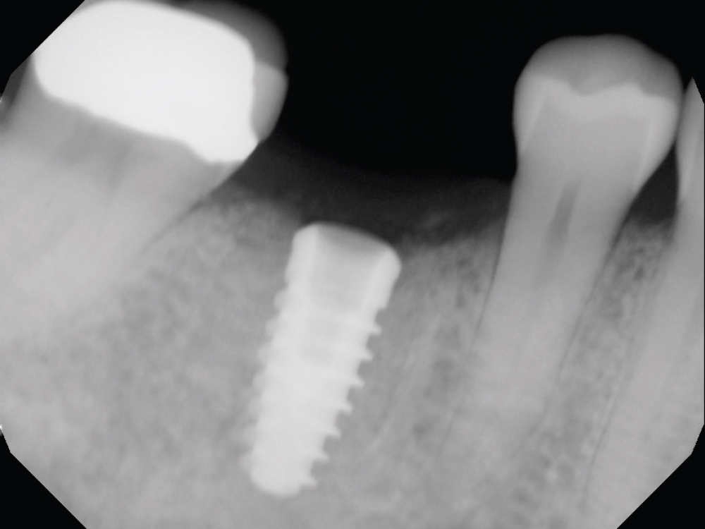
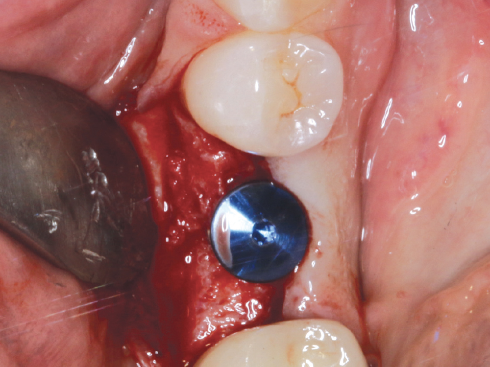
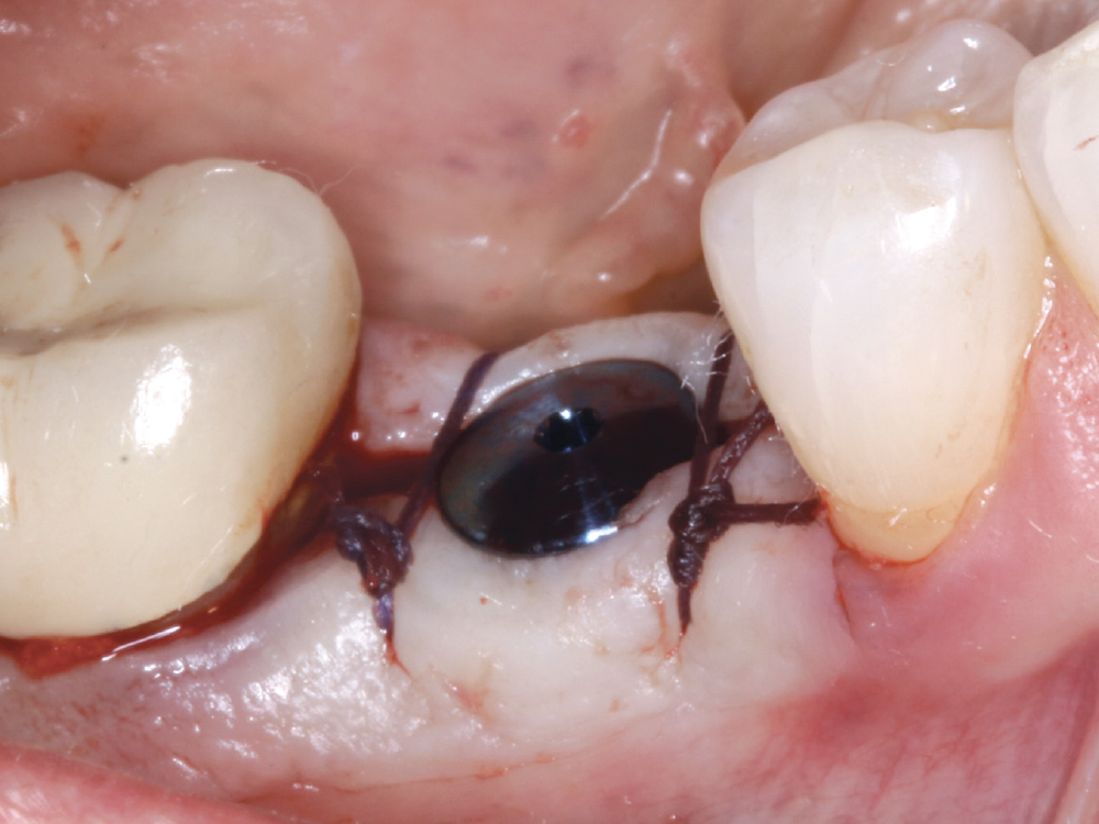
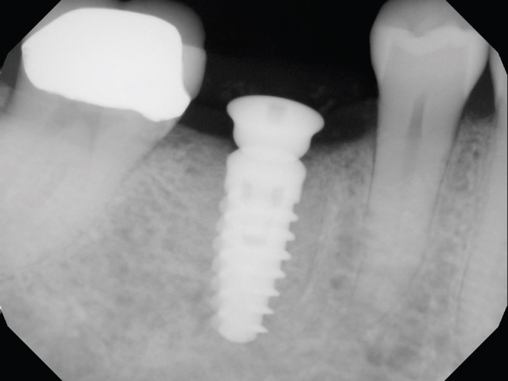
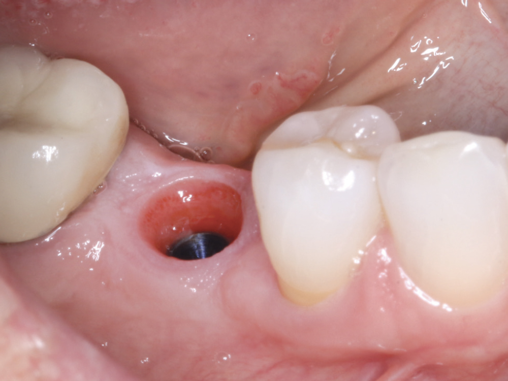
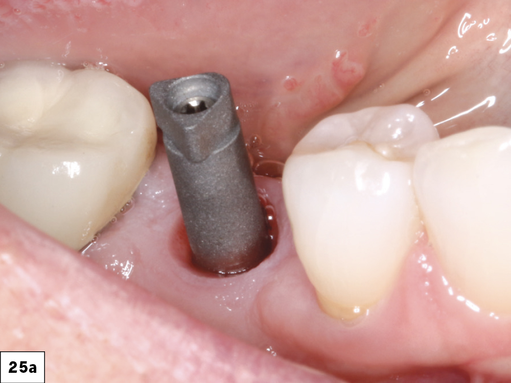
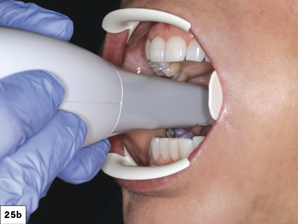
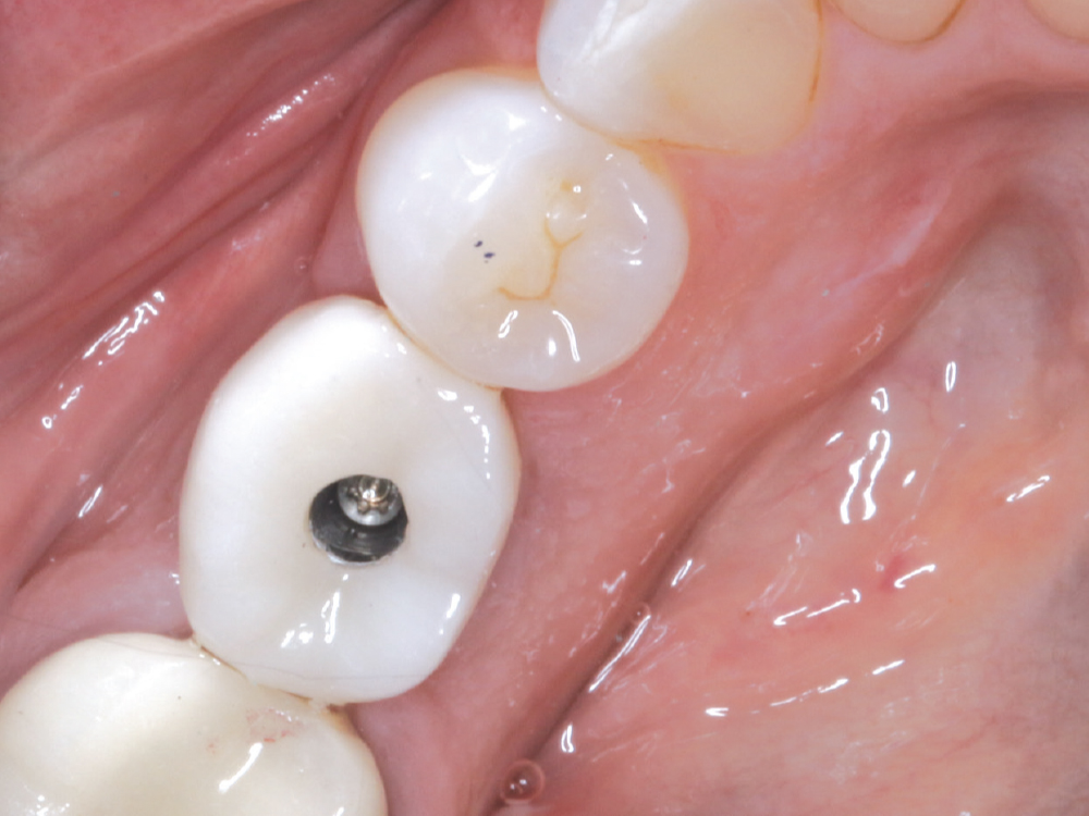
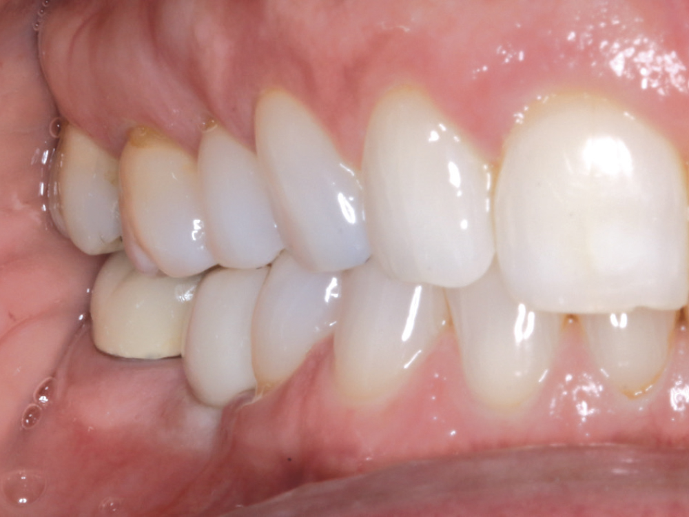
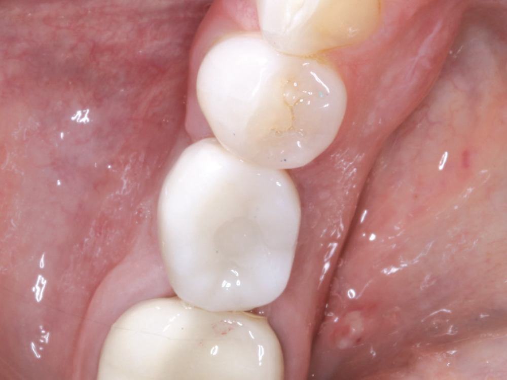
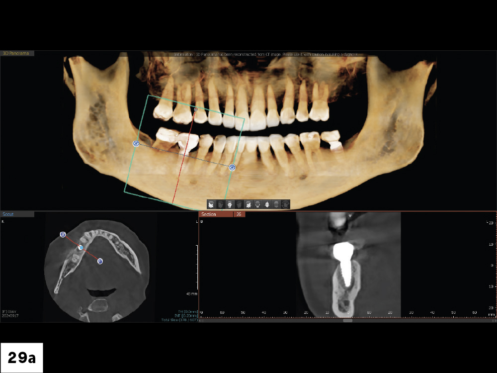
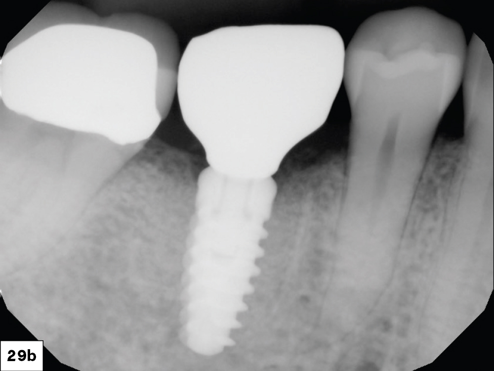
    Case Report


    Figures 1a, 1b: The patient presented with a mandibular molar extraction site that had previously been grafted with cortico-cancellous allograft with a resorbable membrane. The healed site was evaluated for mesial-distal and facial-lingual width, including the amount of attached gingiva on the facial aspect of the edentulous space. The treatment options were communicated with the patient: 

    1. No treatment, which would leave the space edentulous
    2. Fabrication of a conventional, three-unit fixed bridge
    3. Placement of a single dental implant and restoration with an implant-retained crown, allowing for flossing and easier maintenance

    Communication with the patient is paramount to the success of treatment. The use of visual aids, including models or video demonstrations showing similar cases can be helpful.

    Figure 2: A periapical radiograph was taken to evaluate the integration of the graft after four months, the viability of the posterior molar crown, and the position of the adjacent roots.

    Figure 3: A CBCT scan allowed for measurements of vertical and horizontal hard tissue volume and an analysis of vital anatomy, including the mandibular canal and the lingual concavity. The bone density of the grafted site was also determined.

    Figure 4:  After providing adequate anesthesia, the initial incisions were made. A minimum of 2 mm of attached gingiva must be maintained on the facial aspect and should be clearly delineated prior to tissue reflection. If inadequate attached gingiva is present, it must be created by repositioning the attached gingiva to the facial. In this case, there was sufficient attached gingiva present. An Orban knife was used to make a clean crestal incision without any vertical cuts needed. The incision was made about halfway around the necks of the adjacent teeth.

    Figure 5: An envelope reflection was made, moving the crestal tissue to the facial and exposing the boney site. Upon evaluation, it appeared that the bone graft was successful, and the osteotomy could proceed. 

    Note that the lingual tissue was not reflected and remained in position. Incising of mucosal tissue with a vertical incision releases prostaglandins and histamine, and it may result in greater postoperative discomfort, swelling and potential bruising. Eliminating any vertical incision into mucosal tissue provides a more comfortable postoperative experience and allows the tissue to be easily repositioned following implant placement.

    Figure 6: A 1.5-mm-diameter twist drill was used to penetrate the crestal bone. The drill was positioned in the center of the ridge mesial-distally. The implant motor speed ranges from 800–1,200 RPM at 25 Ncm of torque, which I saved as a preset in the implant motor.

    Figure 7: The drill entered the available hard tissue only enough to stabilize the drill to allow for a radiograph. Any adjustments needed to the angulation could be easily made. Here, the head of the handpiece should be moved slightly distal to equalize the spaces mesially and distally.

    Figure 8: The facial-lingual angulation is determined visually by looking at both the angle and position of the pilot drill. Again, any adjustments can be easily made at this early stage. Ideally, the implant should be placed along the central groove of the adjacent teeth.

    Figure 9: Following the determination of angulation using the 1.5 mm initiating drill, the 2.4 mm diameter drill was used to confirm horizontal angulation and vertical depth. The precise depth to be achieved was determined by the preoperative CBCT analysis and by using the apices of the adjacent teeth.

    Any modifications to drill positioning should be completed at this stage. Once complete, the remaining shaping drills widen the osteotomy. It is important to push initially and only once through the cortical plate. If resistance occurs, it likely means you are close to one of two important anatomical structures: the lingual plate or the nerve canal. In the case of such resistance, the site should be carefully evaluated with a new CBCT analysis and review of the osteotomy site with a periodontal probe.

    Figure 10: With the Glidewell HT Implant System (Glidewell Direct; Irvine, Calif.), formerly known as the Hahn Tapered Implant System, the drills are matched to the length of the implant, either 8 mm, 10 mm, 11.5 mm, 13 mm or 16 mm. It has only one notch that is easily visible intraorally and digitally with radiographs. The intent is to widen the osteotomy and constantly evaluate angulation in both dimensions.

    Figure 11: A radiograph illustrated the crestal position and the apical placement using the apices of the adjacent teeth as a guide.

    Figure 12: Mesial-distal and facial-lingual positioning appeared satisfactory, which made the final restoration simple and predictable.

    Figure 13: Once angulation and depth were confirmed, the 3.5 mm x 10 mm shaping drill was used to widen the site. This tapered drill was 0.5 mm smaller in diameter and 1 mm longer than the implant. The widest part of the drill was placed to the crest, which was easily verified by the facial reflection of the tissue. Many errors with dental implants are due to positioning the implant too far facially. The tissue reflection allows for easy determination of proper placement.

    Figure 14: Positioning of the shaping drill was confirmed radiographically with the widest portion directly at the crest of the edentulous ridge and the apex, following the apices of the adjacent roots. The drill was 1 mm longer than the implant itself, providing a margin of safety for vital anatomy when the implant was torqued into place.

    Figure 15: The process of widening the osteotomy continued with the 4.3-mm-diameter drill, following the same protocol, including radiographic verification.

    Figure 16: A unique feature of the Glidewell HT Implant Surgical Kit is the ability of the drills to harvest viable bone in the flutes. The drills are sharp, and removing bone from them provides autogenous graft material, if necessary, to repair any potential defects.

    Figures 17a, 17b: The process continued with the final 5-mm-diameter shaping drill. Ideal preparation was confirmed with a radiograph.

    Figures 18a, 18b: The 5 mm x 10 mm Glidewell HT Implant was removed from its packaging, and the motor slowed to 25 RPM at 35 Ncm of torque. The implant was slowly threaded into the osteotomy site. The motor handpiece was used to initially engage the implant and stopped prior to complete seating. At this juncture, our concern was the implant’s position and not torque, although torque should be recorded.

    Figures 19a, 19b: To correctly monitor final torque, a torque wrench was used to position the implant to the crest of the ridge. This was verified visually.

    Figure 20: A radiograph confirmed that the implant position was flush with the crest and demonstrated that no vital anatomy was affected. This well-positioned implant set a foundation for an easily fabricated implant-retained crown.

    Figure 21: Rather than place a flat cover screw and bury the implant, a 3-mm-tall healing abutment was placed into the implant. This allowed for tissue growth around the healing abutment and eliminated the need for another surgical procedure after integration of the implant. The healing abutment was torqued to 25 Ncm and would not loosen with patient and tongue manipulation. If implant placement does not yield the minimum of 25 Ncm of torque, a cover screw should be placed and the tissue sutured over the top.

    Figure 22: Because the envelope flap was made without any vertical incisions into mucosal tissue, the reflection was easily replaced with two simple Reli® REDISORB® PRO PGA sutures (available through Glidewell Direct; Irvine, Calif.).

    Figure 23: A radiograph was taken to confirm implant positioning and the complete seating of the healing abutment. Note the platform design with the abutment components inside the implant body, eliminating any microgap at the connection.

    Figure 24: Following three months of implant integration, the healing abutment was removed, and the tissue cuff was evaluated.

    Figures 25a, 25b: A Glidewell HT Implant Titanium Scan Body (Glidewell Direct; Irvine, Calif.) was threaded in place. An intraoral scanner was used and the information was sent to the laboratory.

    Figure 26: The final screw-retained BruxZir® Full-Strength crown was placed and torqued to 35 Ncm.

    Figure 27: Occlusion was checked along with proximal contacts.

    Figure 28: Teflon tape was placed into the access hole to protect the screw and the restoration. The access hole was then sealed with composite.

    Figures 29a, 29b: The final screw-retained restoration was verified with a post-treatment CBCT and periapical radiograph.

    CONCLUSION

    Following a proven recipe results in higher levels of treatment success. Taking a “crown-down” approach by imagining the final restoration in place helps the practitioner determine implant placement and maximize osteotomy design and emergence profile. The recipe for success includes verifying each step along the way with the ideal end result in mind.