Full-Arch Immediate Loading Using a Multi-Level Surgical and Prosthetic Guide (1 CEU)

May 30, 2023
 image
Taylor Manalili, DDS, DICOI
 image
Paresh B. Patel, DDS
Patient with full-arch implant prosthesis

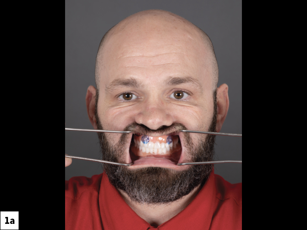
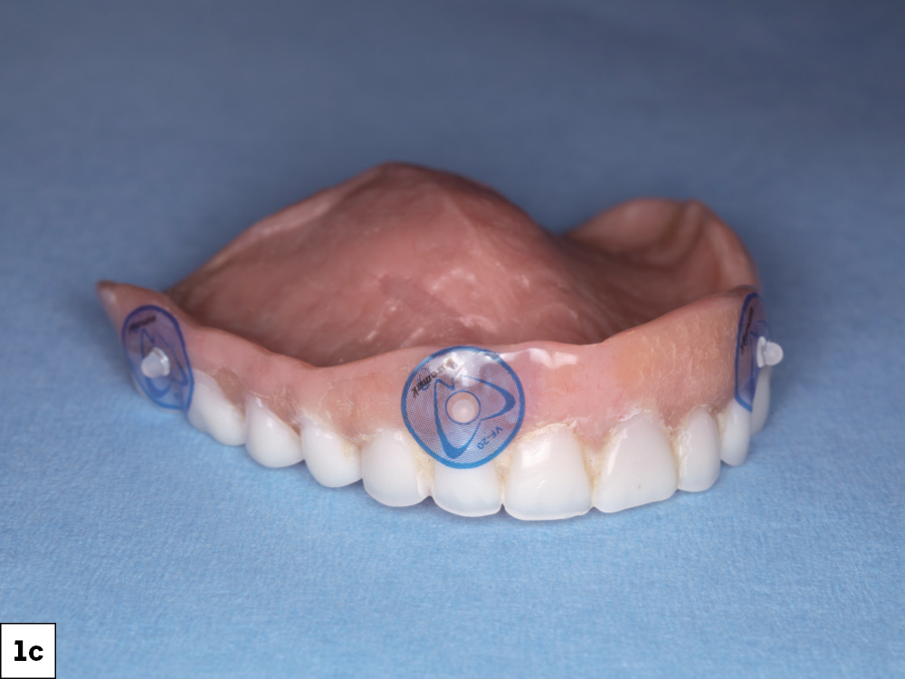
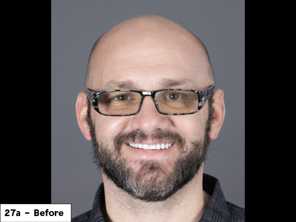
This patient presented wearing upper and lower complete dentures. While the removable dentures fit well, were easy to maintain, and provided acceptable esthetics, the patient sought a fixed prosthesis as a long-term solution.

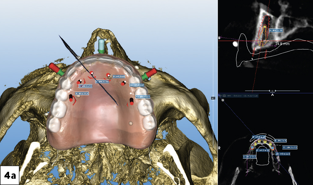
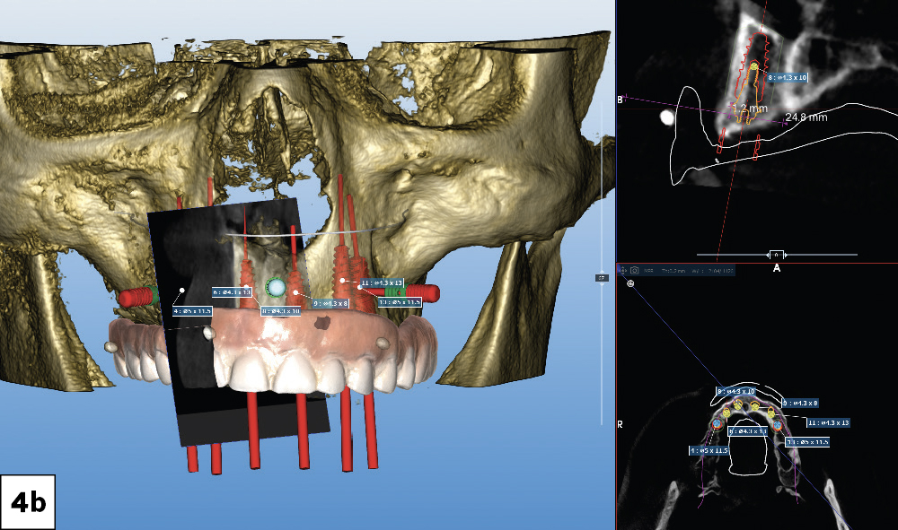
Prosthetically driven treatment planning requires careful collaboration from the lab, the restorative dentist and the surgeon. Based on our treatment goals for this case, we selected a multi-level surgical guide (Glidewell; Newport Beach, Calif.) for increased predictability and efficiency. In this case report, we will elaborate on the treatment of the maxillary arch utilizing a multi-level guided surgery protocol, from the treatment plan to the delivery of the provisional screw-retained implant prosthesis.
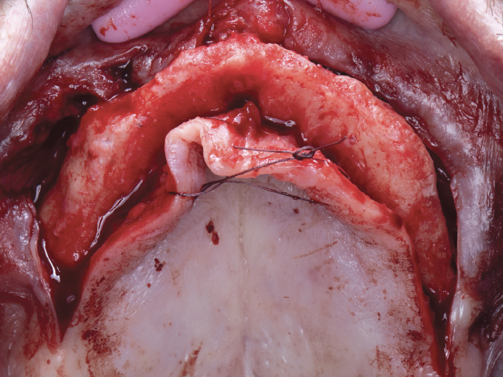
PREPARATION

Verifying fit of implant in patient mouth

Figures 1a–1e: This case began with verifying the fit and esthetics of the patient’s existing denture. It is important that the denture utilized for implant planning is well-fitting. The initial records for implant planning followed the dual-scan CT protocol.

LEARN MORE

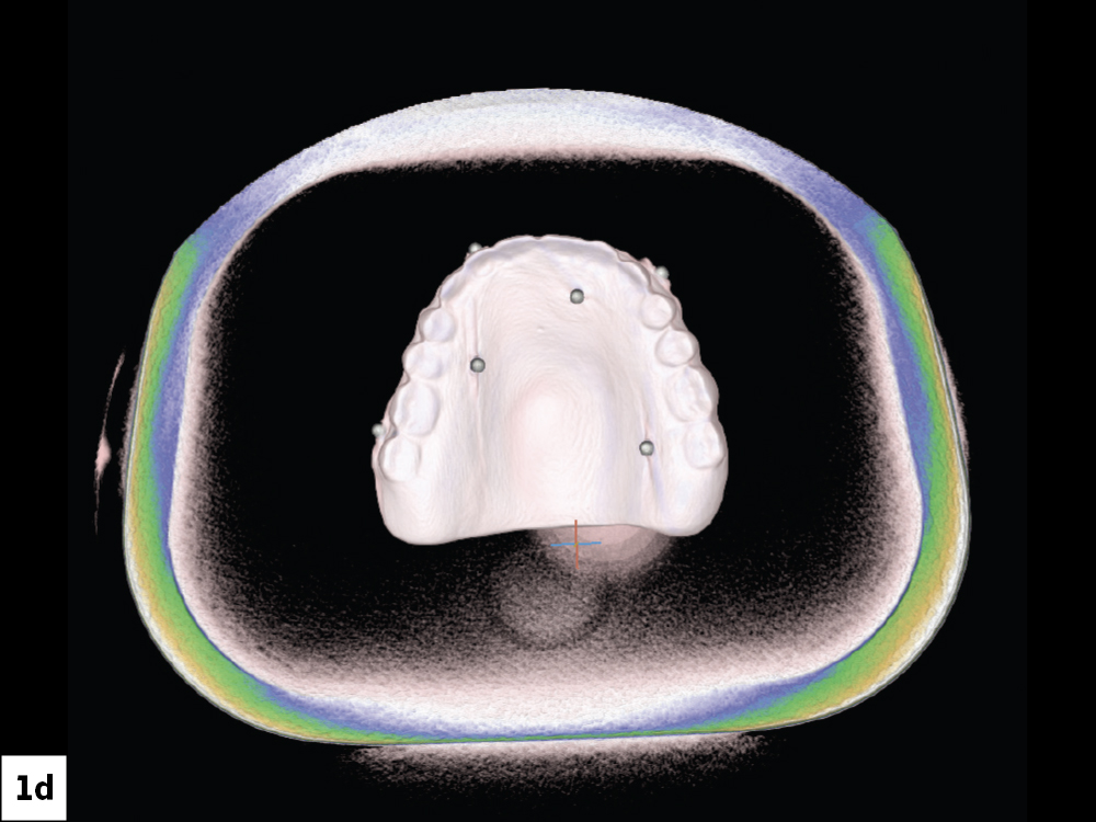
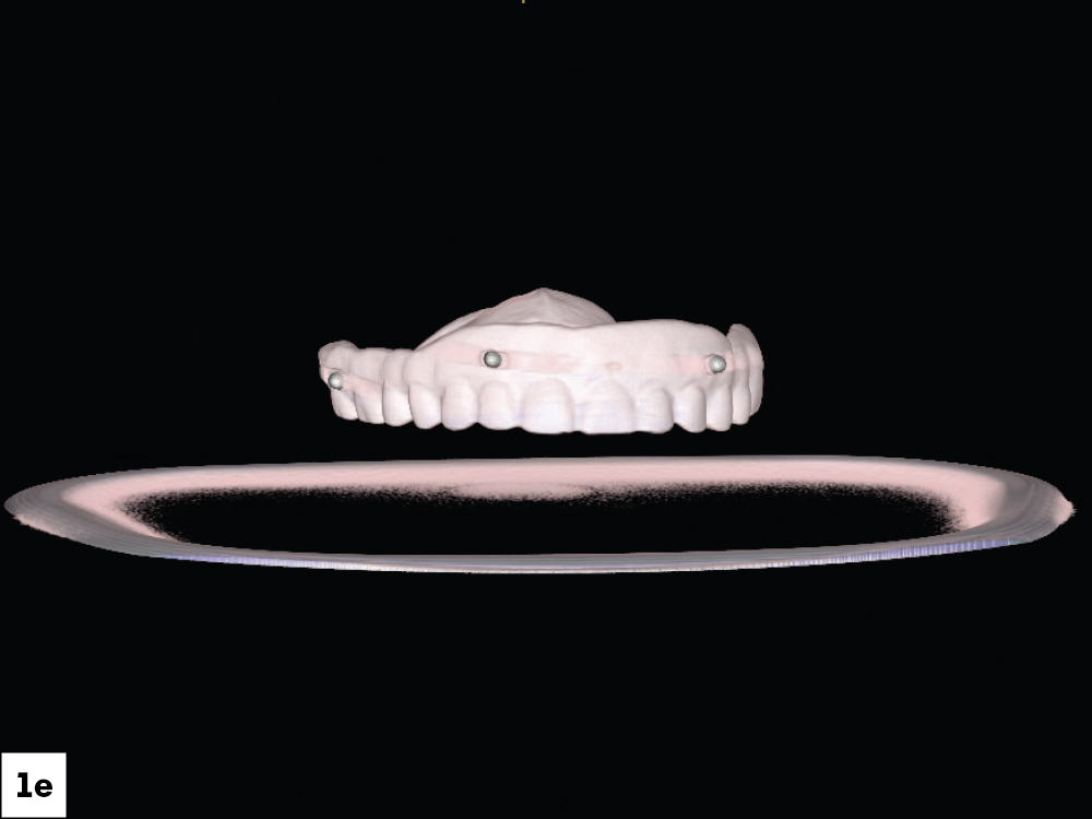
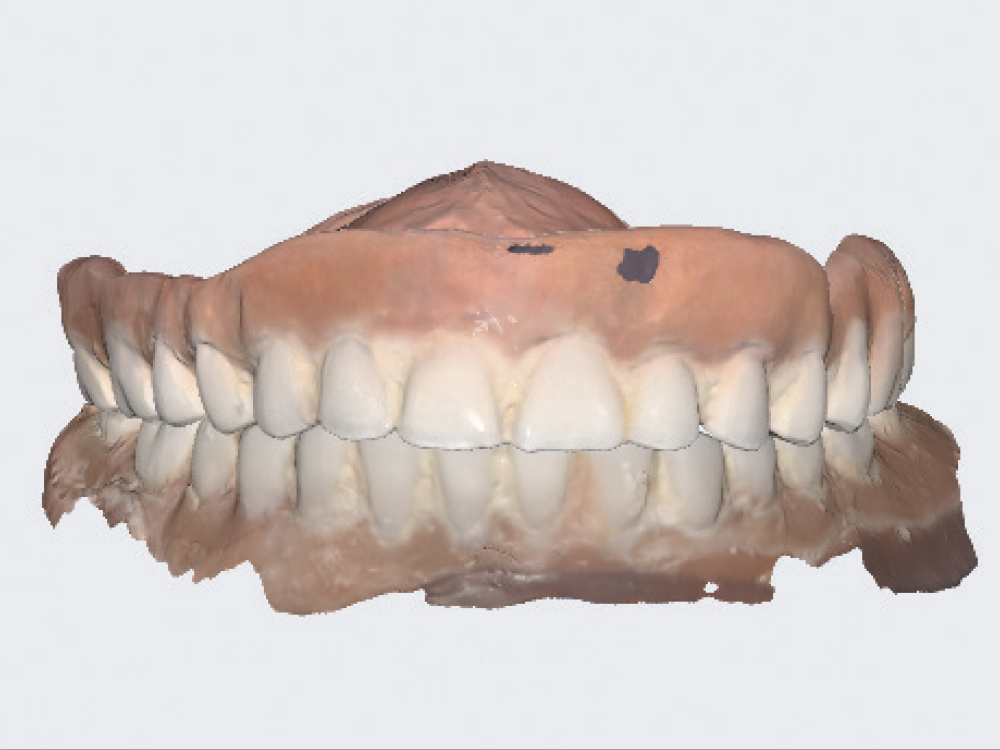
The dual-scan protocol is essential to achieving a predictable outcome for your full-arch guided surgery cases. You can find it by visiting glidewell.com/dtp.

Figure 2: Because the goal at the time of surgery was to immediately load the implants, a prosthesis was fabricated prior to surgery using the pre-existing denture as reference. To aid in the fabrication, an intraoral scan with the Medit® i700® wireless device (Medit Corporation; Seoul, Republic of Korea) was utilized to duplicate the dentures.

Figure 3: Full-face smile images were taken to help with the planning. The full-face photograph helps identify several important factors. The high smile line shows the tooth and gingival display, which allows us to determine the need for hard- or soft-tissue augmentation based on the restorative goal. This is critical to evaluate in the surgical planning phase to better provide the desired restorative outcome. The existing smile line is easily seen in this figure and can be used to guide the esthetics of the immediate provisional.

Figures 4a, 4b: The Glidewell Digital Treatment Planning (DTP) department used the patient’s tooth position on the existing dentures to help determine the optimal positioning of the implants. The tooth position aids the DTP department in optimizing implant positioning to support the desired restoration and assists the team in selecting the correct height and angle of multi-unit abutments (MUAs) to ensure the access channels of the fixed prosthesis are in the best position possible.

Figures 5a, 5b: The immediate full-arch provisional was also designed as part of the treatment plan, replicating the tooth position of the denture as the patient was happy with the esthetics of the denture.

MULTI-LEVEL SURGICAL GUIDE

The multi-level surgical guide is a “stackable” approach to full-arch implant surgery and immediate loading that provides maximum efficiency and predictability with what has traditionally been a complex surgical and restorative procedure.

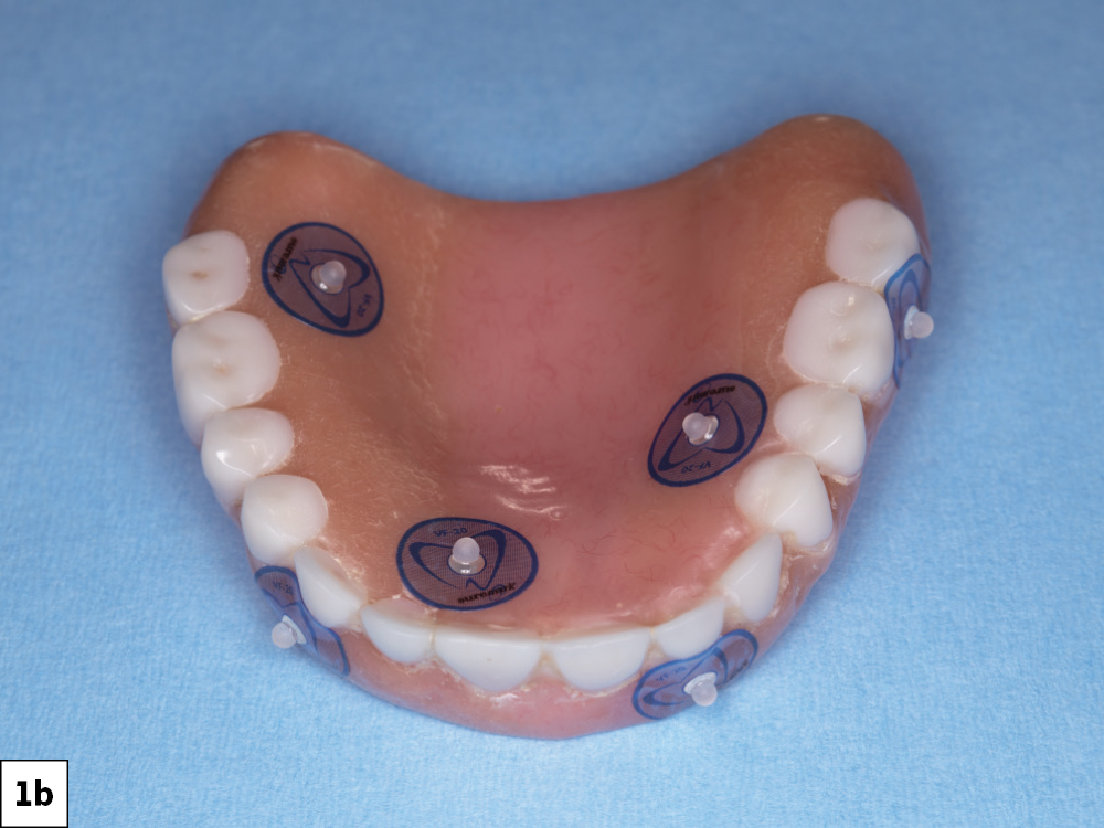
Implant Verification Prosthesis
The implant verification prosthesis (IVP) is connected to the titanium cylinders on the day of surgery and then kept by the restorative dentist. The IVP can be utilized when it is time to fabricate the definitive prosthesis.

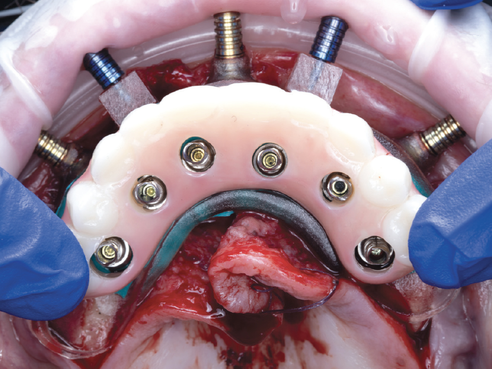
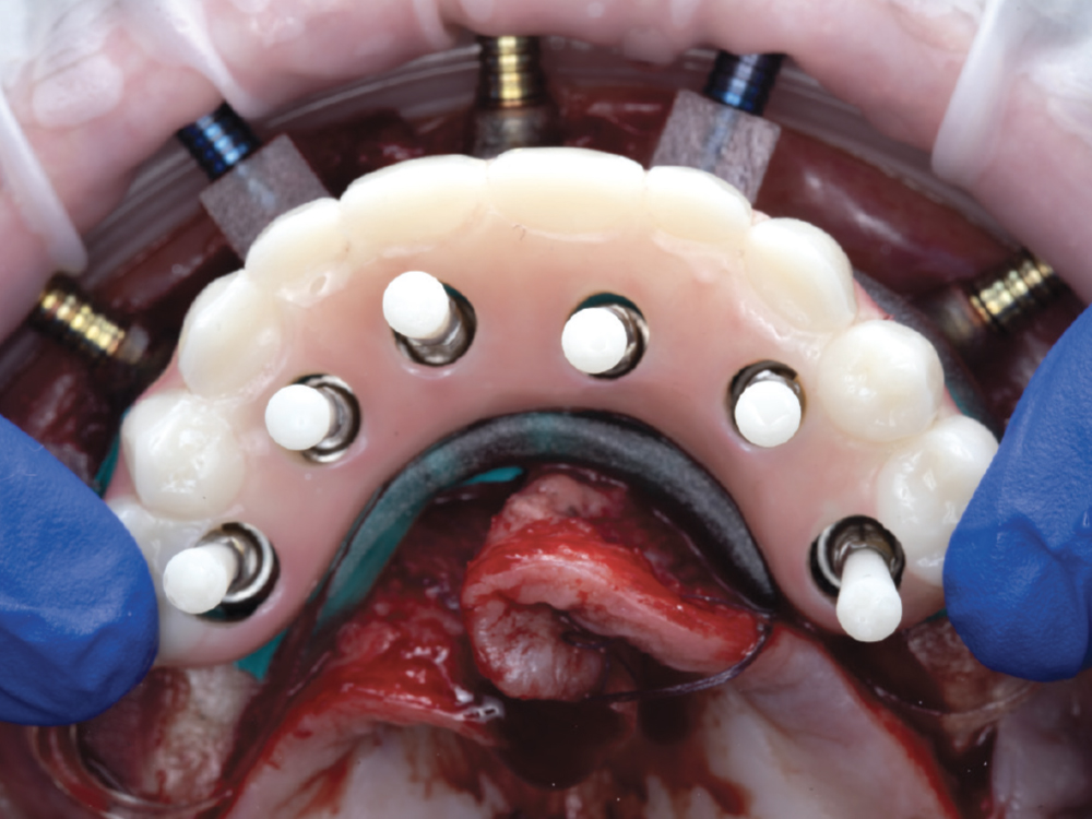
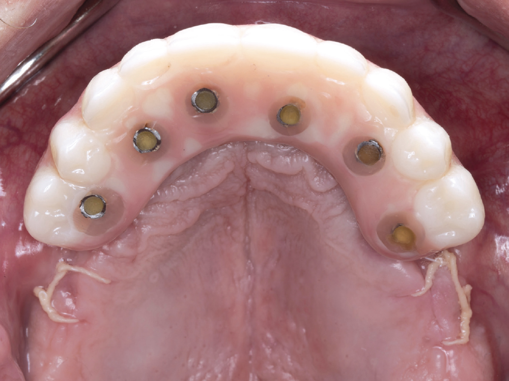
Immediate Fixed Screw-Retained Provisional Implant Prosthesis
The immediate provisional implant prosthesis is luted to the titanium cylinders on the day of surgery and delivered to the patient to wear until the implants are ready for fabrication of the definitive prosthesis.
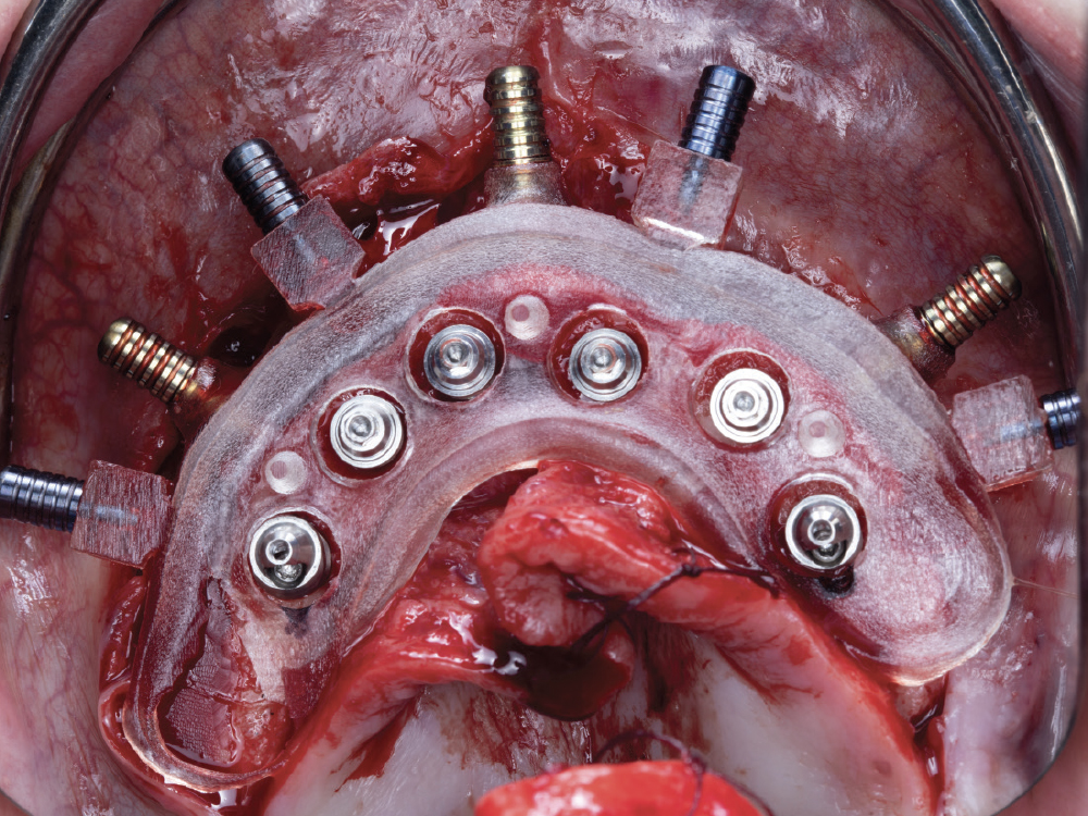
Temporary Cylinders
The temporary cylinders are connected to the multi-unit abutments and then luted to the immediate provisional implant prosthesis and implant verification prosthesis.

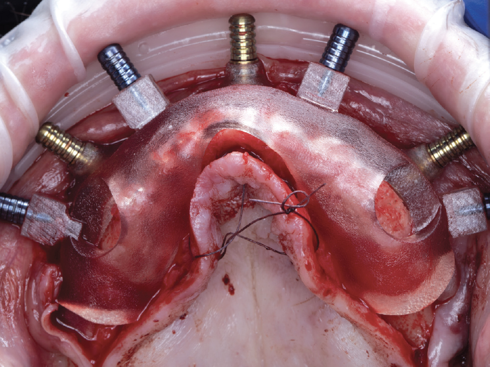
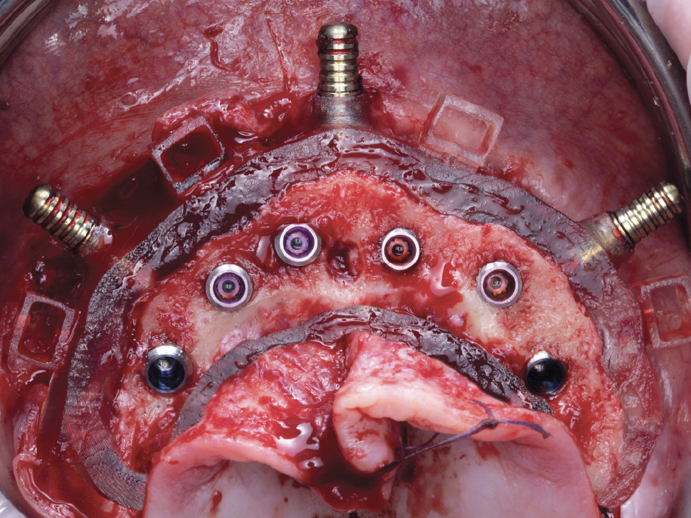
Multi-Unit Abutments
Available in straight or angled, 17 or 30 degrees, these abutments seat between the implants and the prosthesis. They allow for the correction of implant angulation to improve screw-access hole locations. They can assist in leveling the restorative platform for easier restoration design and soft-tissue maintenance.

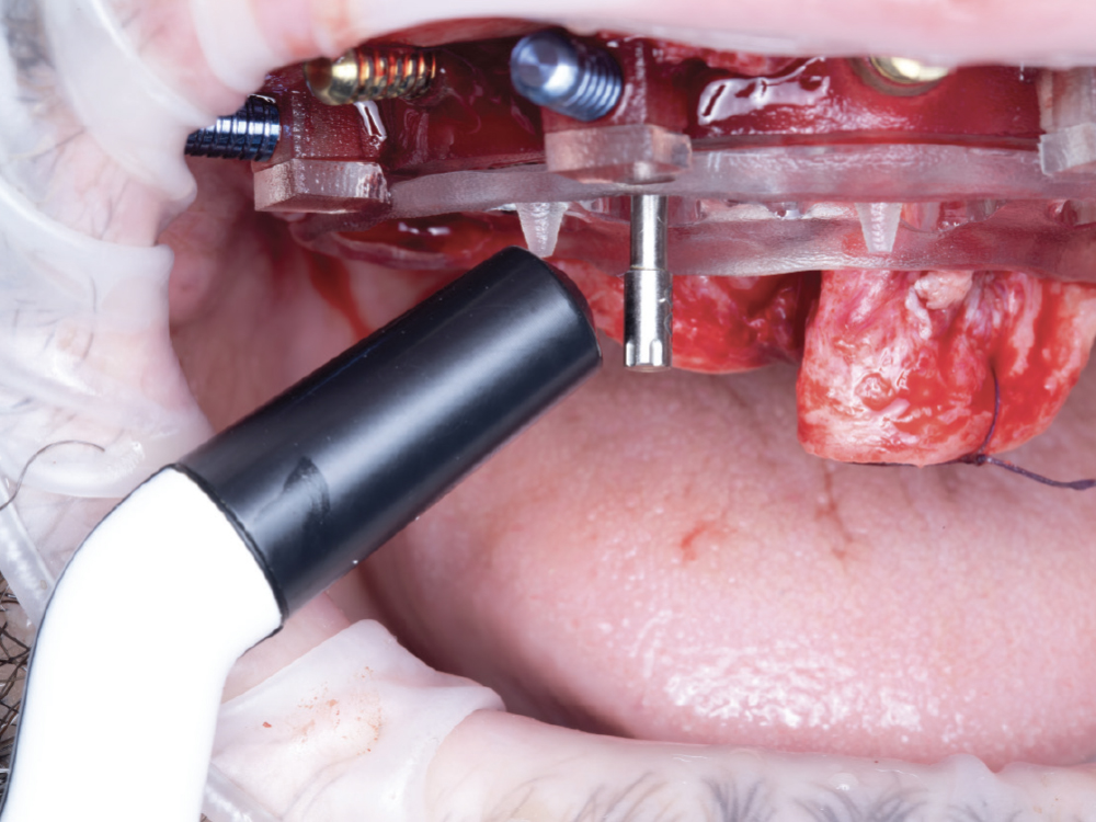
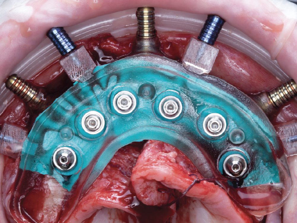
Prosthetic Delivery Guide
The prosthetic delivery guide has direction indicators for easy placement of multiunit abutments. The pegs on the delivery guide allow for the positioning of the immediate provisional prosthesis and the IVP.

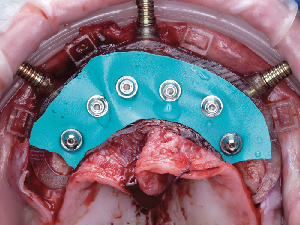
Custom Gasket for Relining Prostheses
The custom gasket is designed to fit snugly around each of the multi-unit abutments, laying underneath the prosthetic delivery guide. This gasket helps prevent the restorative pick-up material from contaminating the surgical site.
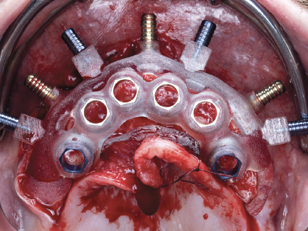
Osteotomy Guide
The osteotomy guide allows for the placement of the implants in the exact positions determined by the digital treatment plan. The guide is compatible with any implant system that utilizes a guided drill system.

Mounting Guide
The mounting guide allows for the placement of the foundation guide. Predesigned windows in the mounting guide allow for visualization of the underlying bone when securing the foundation guide in place.

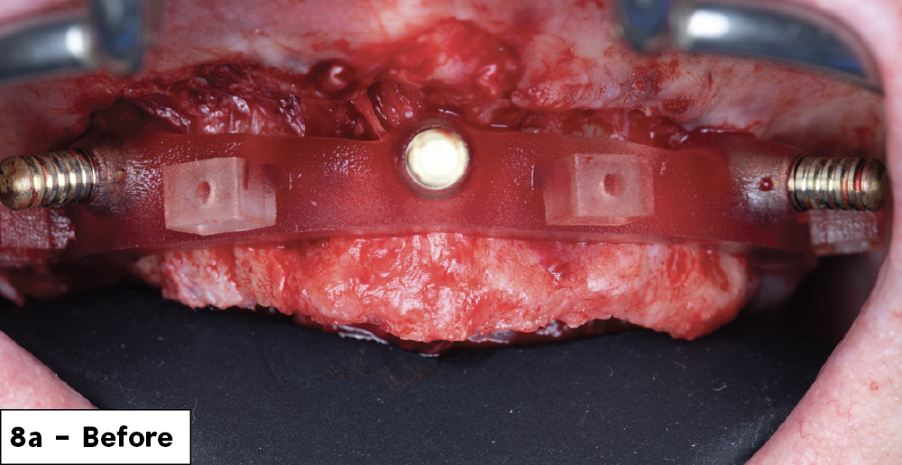
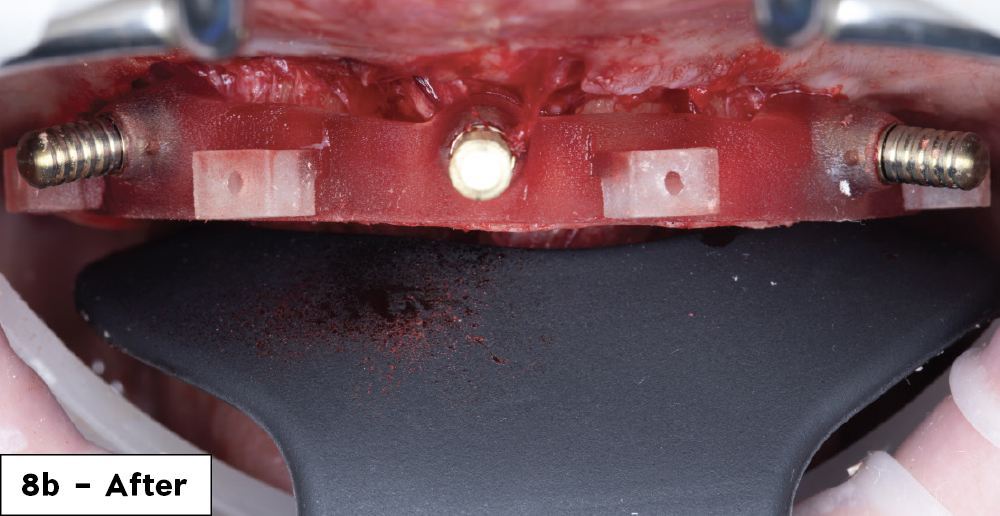
Foundation (Bone Reduction) Guide
This is the foundation for the surgery. It is delivered to the bone via a bone-supported mounting guide. It is the foundation upon which all the other guides will be seated. Once secured in place, the flat plane of the foundation guide is utilized to reduce the bone to the predetermined level.

Anchor Pins
A 1.5 mm diameter drill is utilized to create the osteotomies for the placement of anchor pins, which are then pushed into position to secure the foundation guide to the bone.

Interlocking Pins
These pins secure the multi-level components together. For ease of transition between the various multi-level componentry, the pins are manually placed and released. Floss holes are included on the handles for safety measures.

3D-Printed Segmented Bone Reduction Model
This model demonstrates the planned bone reduction.

3D-Printed Model
This model demonstrates the bony anatomy of the arch being treated and the post-bone reduction implant placement. 

Note: Surgical guides are customized for individual patients

FOUNDATION GUIDE

Figure 6: First, a full-thickness flap was reflected, extending the flap to ensure the guide was fully seated on the bone.
 

Figure 7: Next, the foundation guide and the mounting guide were connected via the blue interlocking pins. To ensure the guide was seated in the correct position, we utilized the mounting guide to verify the fit by ensuring it was flush with the bone. Once stable, the anchor pin osteotomies were drilled, and yellow anchor pins were placed to secure the foundation guide.
 

Figures 8a, 8b: We removed the blue interlocking pins and the mounting guide, leaving the foundation guide securely in place. The foundation guide was then utilized as a guide for bone reduction. The “before” photo illustrates how much bone needed to be reduced. The “after” photo shows the new bone contours, parallel to the occlusal-facing flat surface of the foundation guide.

The multi-level surgical guide is a “stackable” approach to full-arch implant surgery and immediate loading.
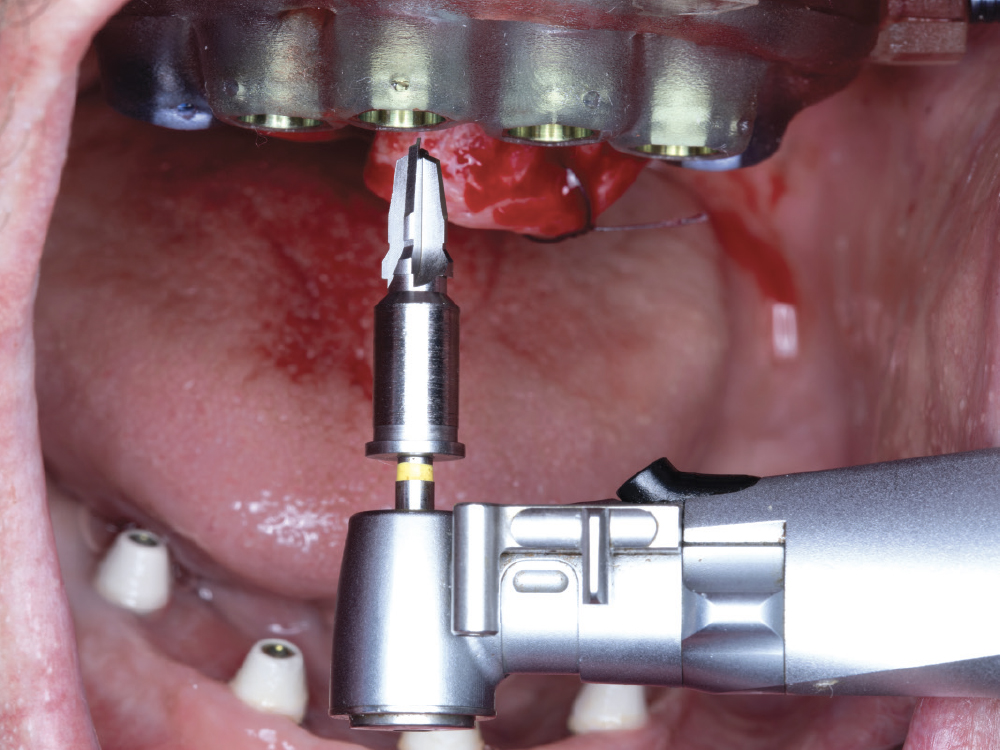
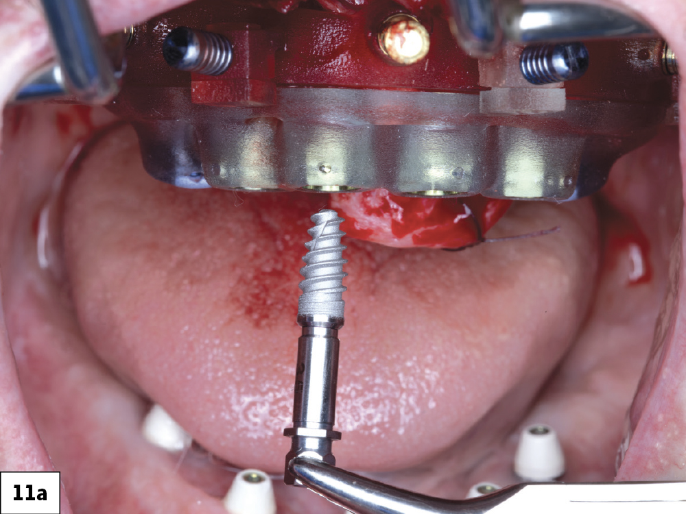
OSTEOTOMY GUIDE

Figure 9: The osteotomy guide was seated on top of the foundation guide, and the blue interlocking pins were re-inserted to secure the guide.
 

Figure 10: With the guide secured, the osteotomies were sequentially drilled following the approved digital treatment plan. The drilling sequence was performed according to the pre-planned guided surgical protocol.
 

Figures 11a, 11b: Hahn™ Tapered Implants (Glidewell Direct; Irvine, Calif.) were placed.


Figure 12: After the implants were placed, the interlocking pins and osteotomy guide were removed.

Figure 13: The implant stability quotient (ISQ) value was measured using a Penguin® II osseointegration monitor (available through Glidewell Direct). The acceptable stability range for cross-arch immediate loading with a provisional implant prosthesis is a measurement between 55 and 85 ISQ.

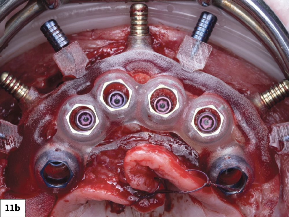
NOTE: Based on the stability of the implant and our plan for prosthetic loading, we select one of the following component options:

  • Cover screw (hand-tighten)
  • Healing abutment (hand-tighten)
  • Multi-unit abutments (implant manufacturer’s recommended torque value)

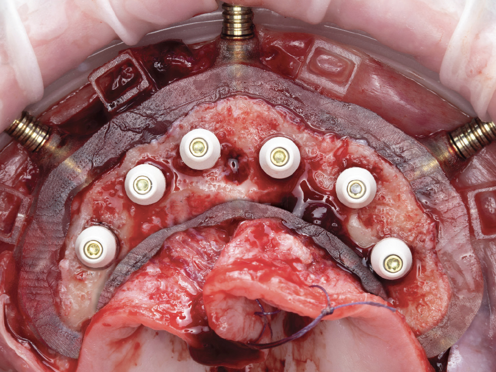
PROSTHETIC DELIVERY GUIDE

Figure 14: The primary stability and torque were sufficient for immediate loading, so we proceeded to seat the prosthetic delivery guide and secure it in place with the blue interlocking pins. The MUAs were then seated and torqued to 35 Nm (the manufacturer’s recommended torque value). The correct orientation of the angled MUAs was indicated on the surgical guide for ease of positioning.

Figure 15: The interlocking pins and prosthetic delivery guide were temporarily removed. This allowed placement of the gasket, which protects the surgical site during the pickup of the cylinders for the immediate fixed screw-retained provisional. The gasket prevents the restorative acrylic from contaminating the surgical site.

Figure 16: Once the gasket was in place, the prosthetic delivery guide with the blue interlocking pins was re-inserted.

Figure 17: The laser-labeled, pre-cut temporary cylinders were seated and hand-tightened into place.

Figure 18: The immediate provisional was seated onto the prosthetic delivery guide. There should be a minimum of 1 mm of space around the titanium cylinders to ensure a passive seat and adequate room for the addition of pickup material. If the minimum 1 mm is not met, adjustment is required.
 

Figure 19: With the prosthesis in position, blockout shims were inserted into each titanium cylinder. This step prevents any acrylic from accidentally covering the access channels during the pickup process.

Figure 20: The pick-up material was flowed into the acrylic channels located on the buccal, lingual and occlusal surfaces, securing each titanium cylinder to the immediate provisional prosthesis.

Figure 21: The prosthesis with the luted titanium cylinders was then removed from the mouth.

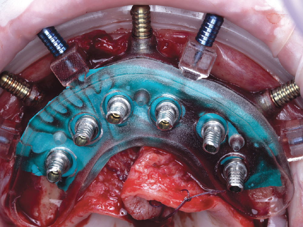
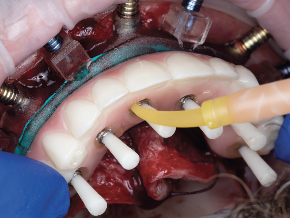
NOTE: Complete the conversion process by performing the following steps with the provisional implant prosthesis outside of the patient’s mouth:

  • Cut cylinders if necessary
  • Fill in voids with composite or pickup acrylic
  • Adjust and polish the prosthesis

If an implant verification prosthesis was also provided for your case, repeat the above steps for it.

Figure 22: The prosthetic delivery guide and gasket were removed. To assist in contouring and suturing the soft tissue, MUA cover caps were hand-tightened into place. The anchor pins were then removed, allowing the foundation guide to be detached.

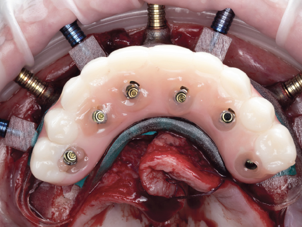
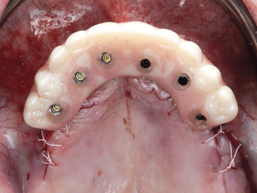
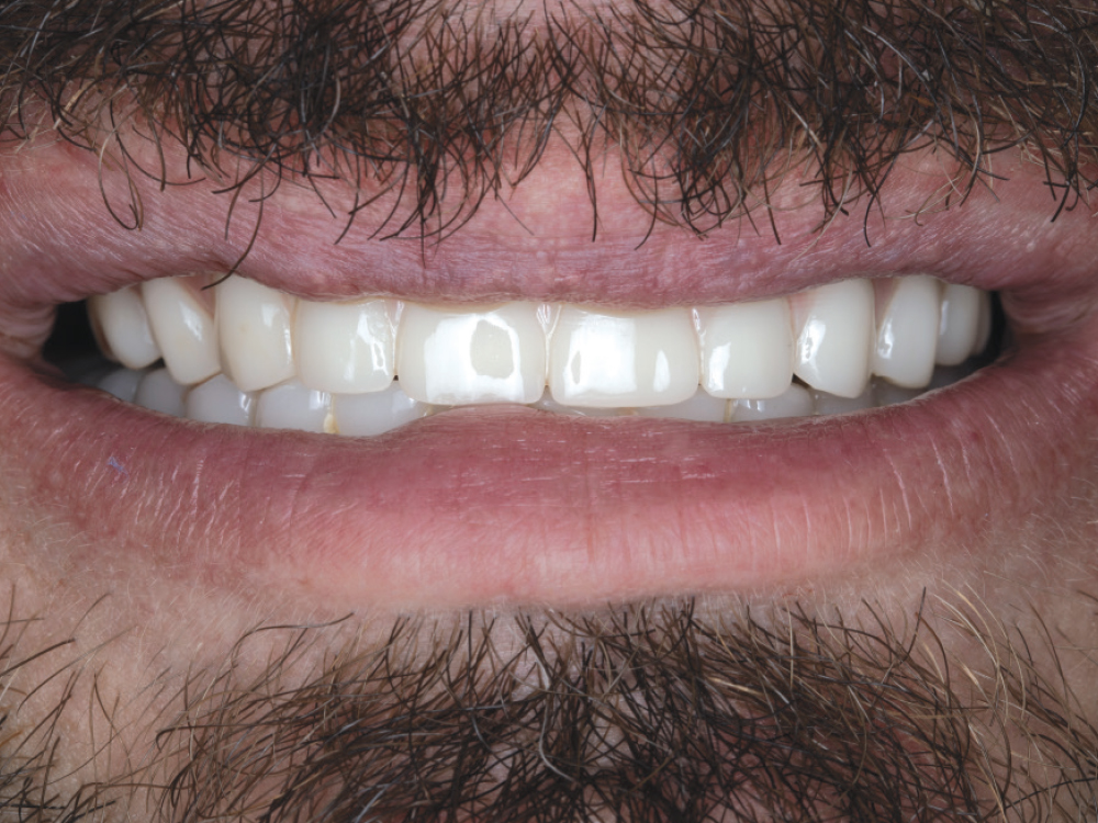
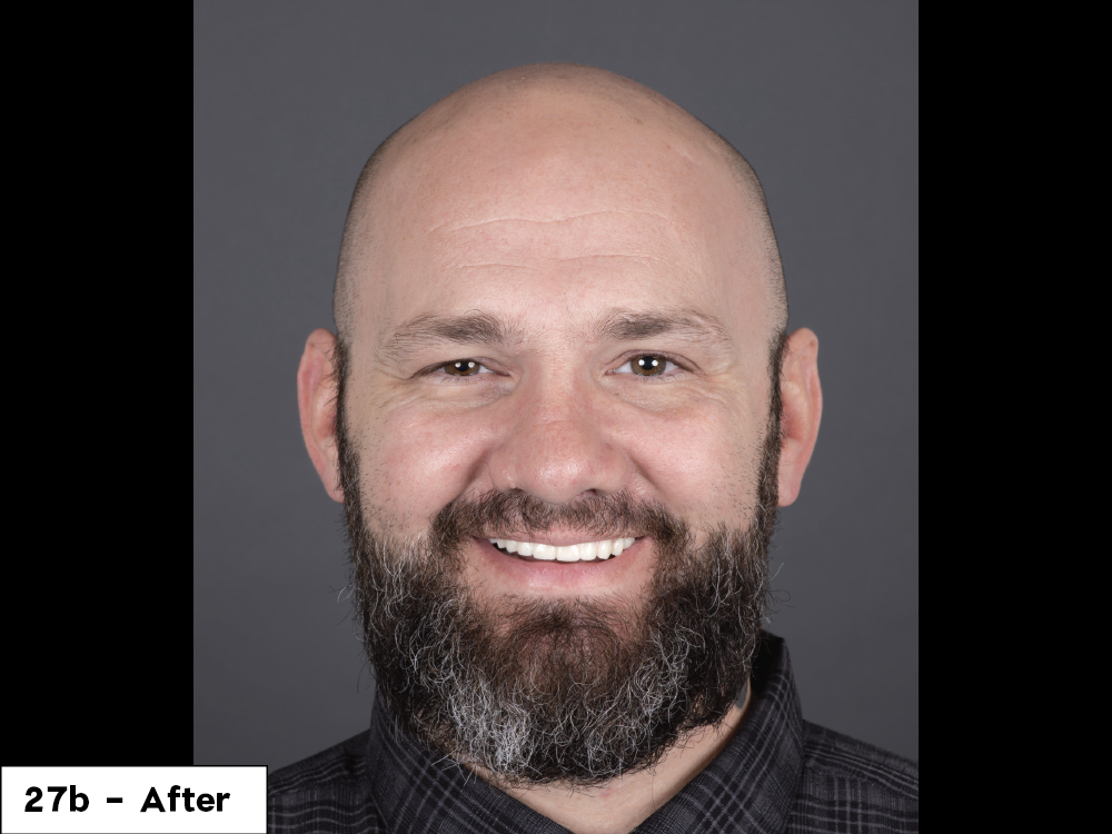
DELIVERY OF PROVISIONAL IMPLANT PROSTHESIS

Figure 23: Once suturing was completed, the MUA temporary healing caps were removed and the provisional was seated. The provisional was torqued to 15 Nm (the manufacturer’s recommended torque value).

Figure 24: Teflon® tape was placed into the access channels to protect each prosthetic screw. The access channels were then closed with Fermit® resin (Ivoclar; Amherst, N.Y.).

Figure 25: With the patient sitting upright, the occlusion was verified. There should be minimal working and non-working contacts, with evenly distributed centric contacts to provide freedom of movement while minimizing lateral stresses on the implants.

Figure 26: The implant positions were confirmed utilizing a post-op CBCT image.

Figures 27a, 27b: The “before” image shows the patient with his initial removable dentures — esthetically sound but lacking the function he desired. In the “after” image, the patient shows off his newly fabricated immediate provisional fixed in the maxillary arch.

CONCLUSION

Advanced procedures like the immediate loading of implants for a fixed full-arch restoration are becoming more predictable with advances in technology. Prosthetically driven guided implant placement allows for optimal restorative outcomes. The multi-level surgical guide will allow you to take your implant practice to the next level, aiding in both surgical and prosthetic predictability.