In this issue:
Full-Mouth Esthetic Restoration: A Winning Collaboration of Chairside and Laboratory
Author
Advances in the digital workflow combined with new restorative fabrication methods have opened up ways to more efficiently treat even the most challenging cases. In this case, I present a process that integrates working with the laboratory and chairside milling to achieve the final esthetic result for the patient. This efficient workflow reduces patient appointments, allows me to work with the dental laboratory when needed and enables me to confidently provide the esthetic remake requested by the patient.
CASE STUDY
The patient presented with complaints about her small, worn teeth. She was dissatisfied with their appearance and felt self-conscious when smiling. She had exposed dentin and failing composite restorations caused by dental attrition complicated by acid erosion. We decided to pursue an esthetically driven treatment plan, using fully sintered crowns instead of implants.
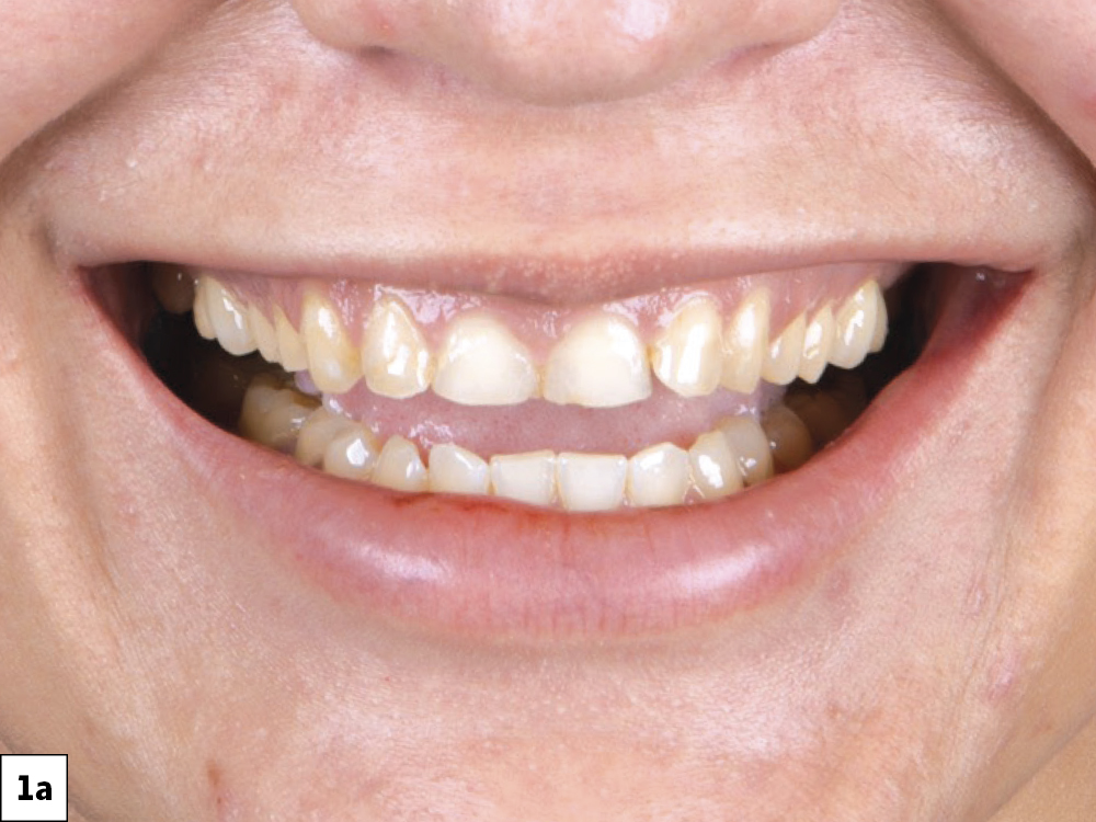
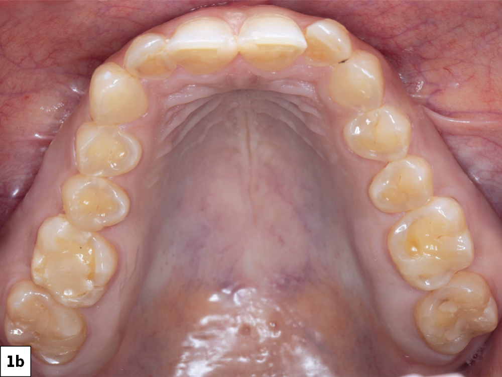
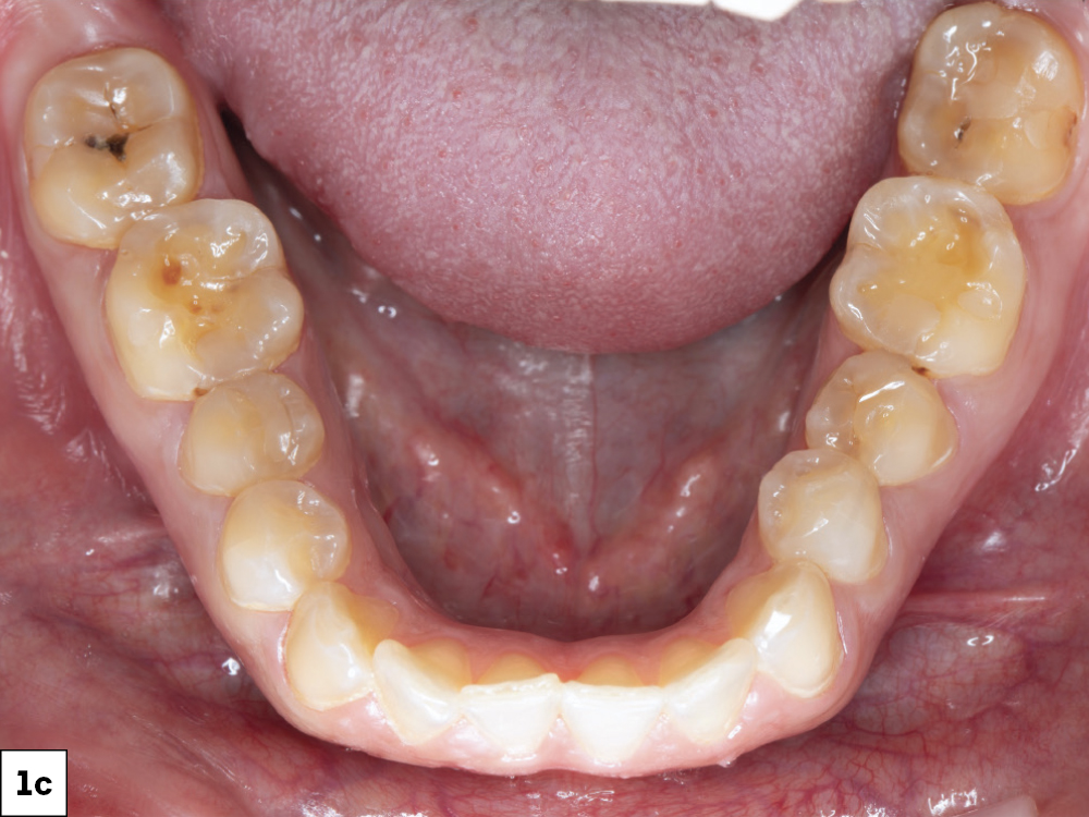
Figures 1a–1c: The preoperative situation showed generalized enamel erosion as well as secondary caries. After the initial impression was taken using the iTero Element® scanner (Align Technology, Inc.; San Jose, Calif.), a treatment plan was developed that focused on esthetics while protecting the patient’s natural dentition.
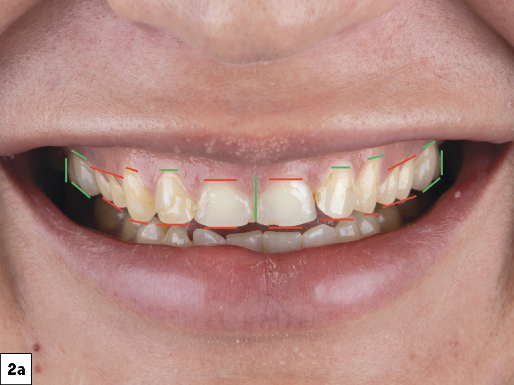
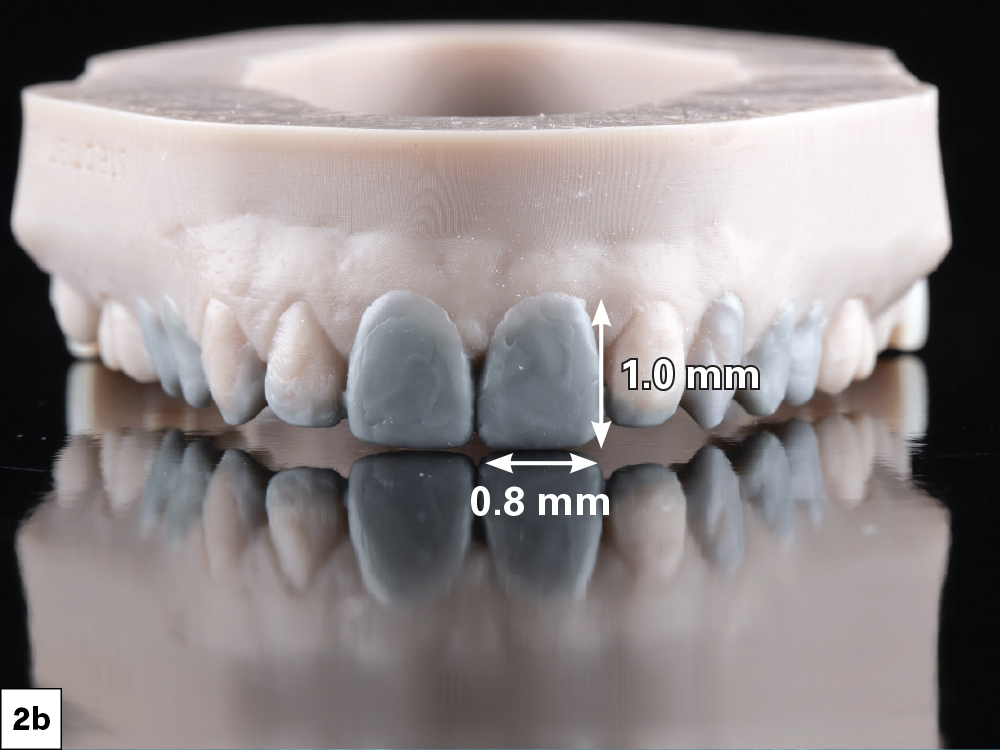
Figures 2a, 2b: It was determined that the midline as well as the anatomical shape of the molars were satisfactory, while the overall length of the anterior teeth and gingival display needed improvement. I used this information to create a facially driven diagnostic wax-up that reflected the desired changes. One general ratio I use as a starting point is that the mesial-distal width of the central incisors should be approximately 80% of their length, although this can vary based on overall esthetics and the desired outcome.
Advances in the digital workflow combined with new restorative fabrication methods have opened up ways to more efficiently treat even the most challenging cases.
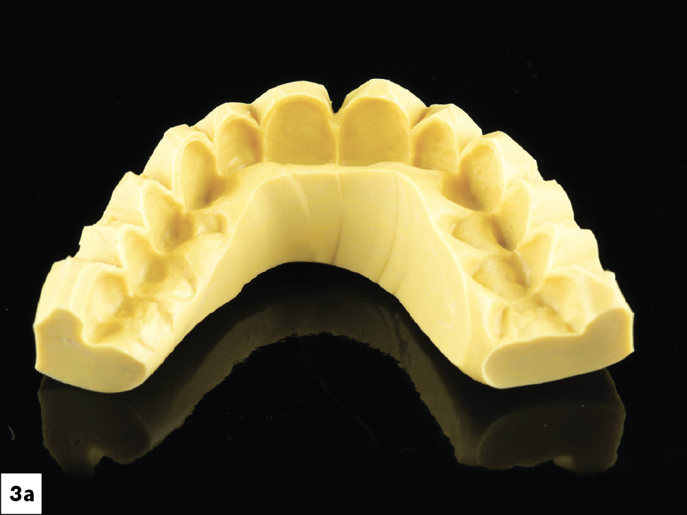
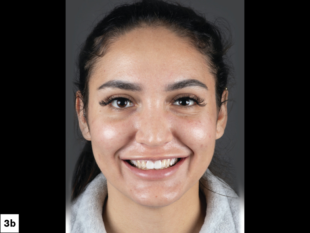
Figures 3a, 3b: The mock-up. Once I was satisfied with the diagnostic wax-up, I used a putty matrix to transfer the design to the patient’s teeth by backfilling with bis-acryl material, giving the patient and myself the opportunity to see how the design looked in her mouth. After confirming the planned esthetic improvements, I used the mock-up to request the BioTemps® Provisionals from the lab. A mock-up was not needed for the lowers, since they would be guided by the maxillary teeth. Depending on preference, either the lab or the clinician can produce the diagnostic wax-up and putty matrix.

Figure 4: Checking gingival contours. The BioTemps Provisionals came with a thermoformed stent, which acts as a positioning guide when seating the provisionals. Because the stent is modeled from the wax-up, it reflects any changes planned for the gingival margin. This allows me to use it as a soft-tissue guide when performing gingivectomy procedures.

Figure 5: Adjusting gingival contours. Using a Waterlase iPlus® tissue laser (BIOLASE, Inc.; Foothill Ranch, Calif.), I followed the contours of the stent while removing soft tissue. Starting on teeth #8 and #9, I moved outward, removing tissue from premolar to premolar. Once completed, I started the tooth preparation.

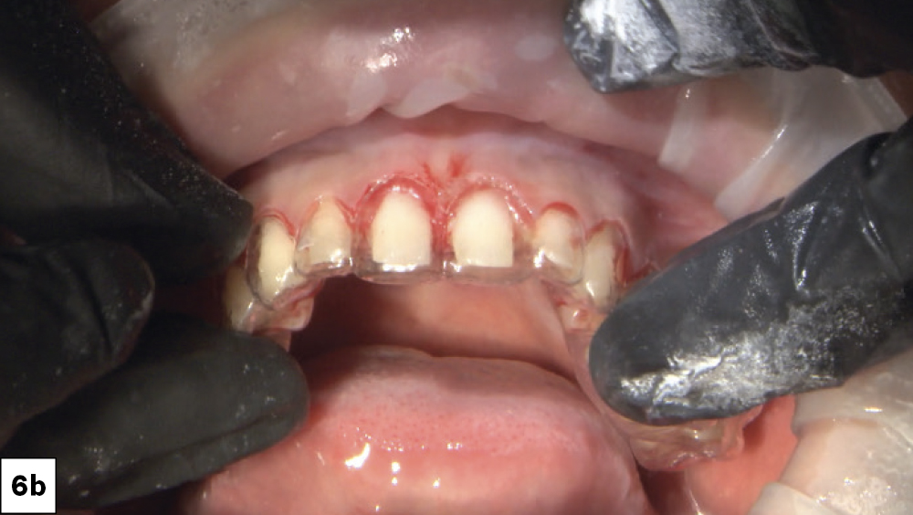
Figures 6a, 6b: I started my preparation with teeth #6–11 so I could use the posteriors as a stabilizer when seating the BioTemps Provisionals. My goal while reducing the teeth was to establish 1.5 mm of clearance from the opposing and a 0.5 mm chamfer margin to provide enough material thickness and strength along the occlusal and the margins. Using the stent as a guide can help visualize if adequate tooth reduction has been achieved.
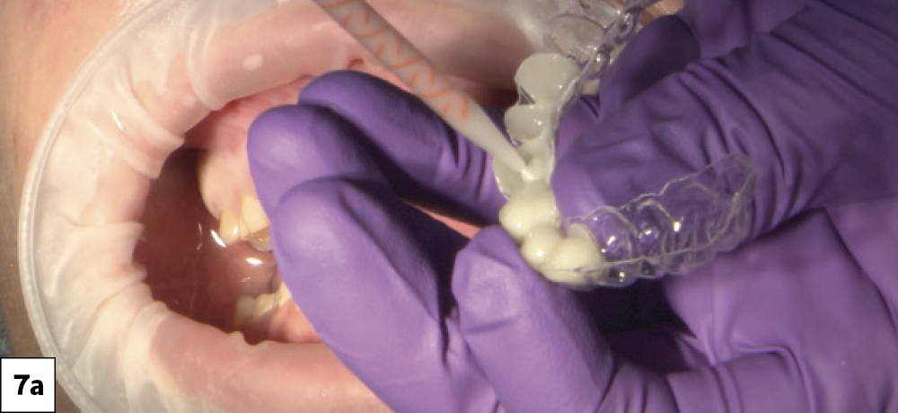
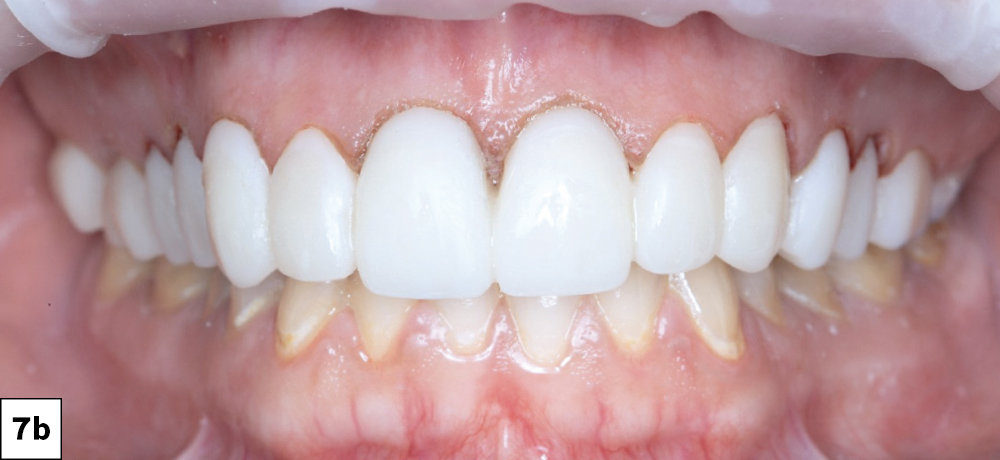
Figures 7a, 7b: Seating the BioTemps. After trying in the BioTemps Provisionals to check for interferences, I used ScotchBond™ Universal Plus Adhesive (3M; Maplewood, Minn.) on the inside surfaces and then flowed Luxatemp® Ultra (DMG America; Ridgefield Park, N.J.) to reline the provisionals. The BioTemps Provisionals were then seated over the prepared teeth (which were lubricated with petroleum jelly to allow for removal of the provisionals). I used the supplied stent as a brace to keep the provisionals in place. After the reline set, I removed the provisionals and trimmed the excess using a diamond bur. Once the anterior teeth were fully prepared and the provisionals were fit correctly, I repeated the same process for the posteriors. The anterior BioTemps Provisionals now served as a support for the seating stent.
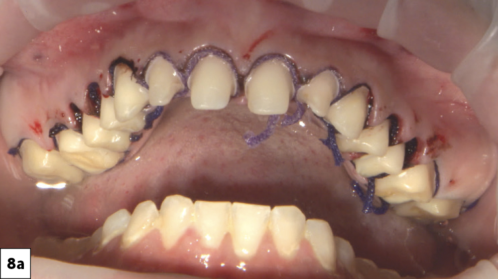
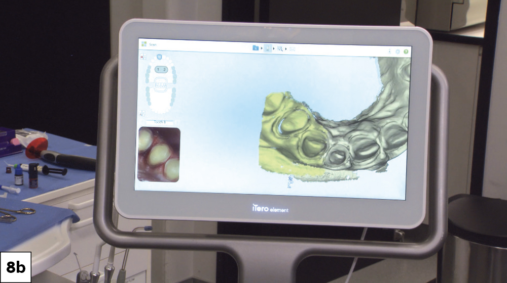
Figures 8a, 8b: Two weeks after the preparation appointment, the patient returned for the final impressions. I used an intraoral scanner to first capture impressions of the BioTemps Provisionals, known as a “pretreatment scan,” so I could use the impressions as a design reference for the final restorations. Once complete, I removed the provisionals and cleaned the prepared teeth with pumice. I then used Ultradent Ultrapak™ size #1 cord (Ultradent; South Jordan, Utah) to expose the margins before capturing the final impressions.
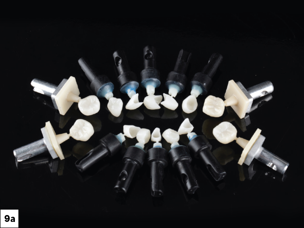

Figures 9a, 9b: Using fastdesign.io™ Software and Design Station in conjunction with the fastmill.io™ In-Office Mill, I designed and fabricated the restorations in office. I opted for BruxZir® NOW crowns for the molars and BruxZir Esthetic NOW crowns for the anterior and premolars. I then used a 3D-printed model of the patient’s prepared teeth to try on the milled crowns. This allowed for a fit check and final contouring adjustments.
FINAL CROWN DELIVERY
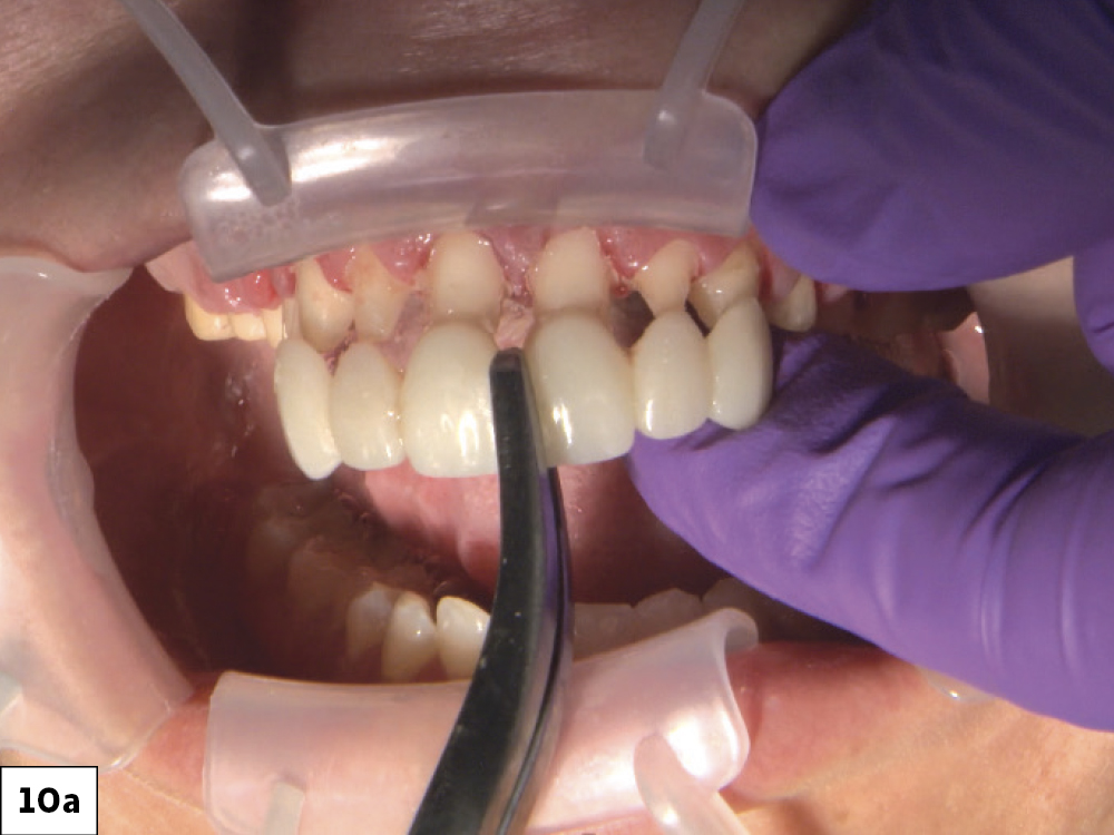
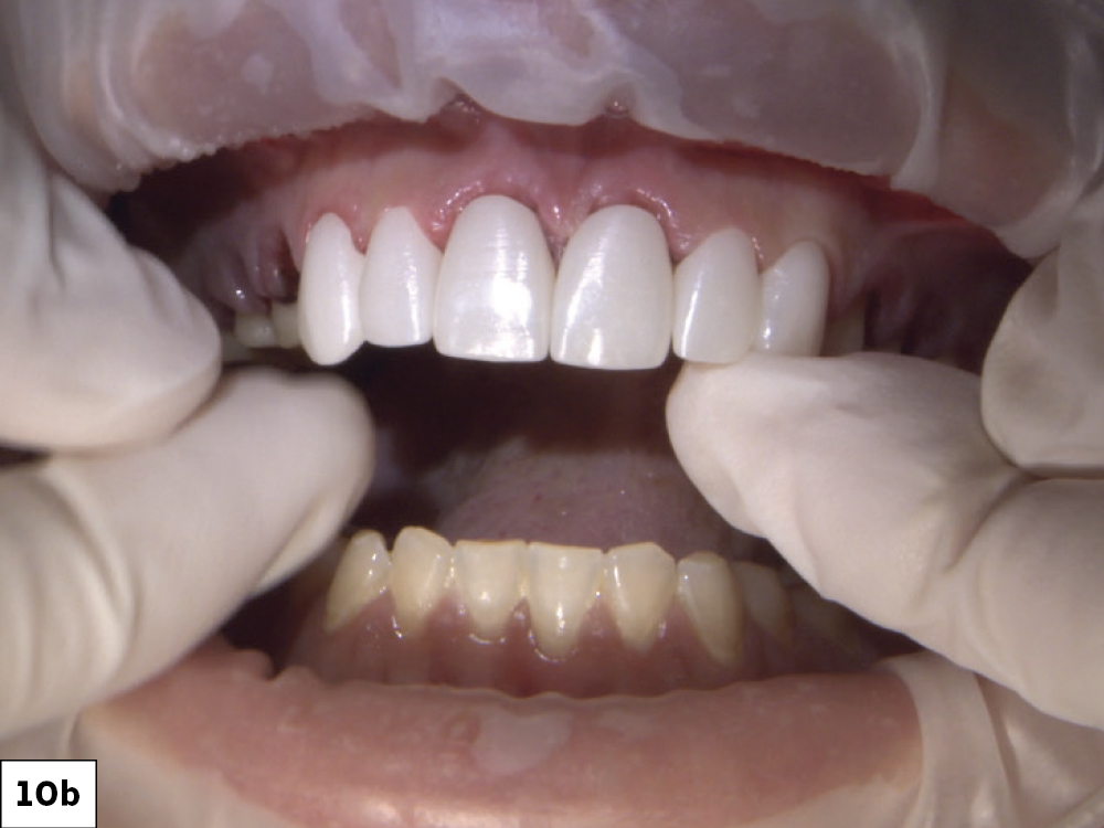
Figures 10a, 10b: During the final delivery appointment, I removed the provisionals, making sure to clean any excess temporary material from the preparations. Next, I tried on the crowns to evaluate fit, proximal contact and occlusion.
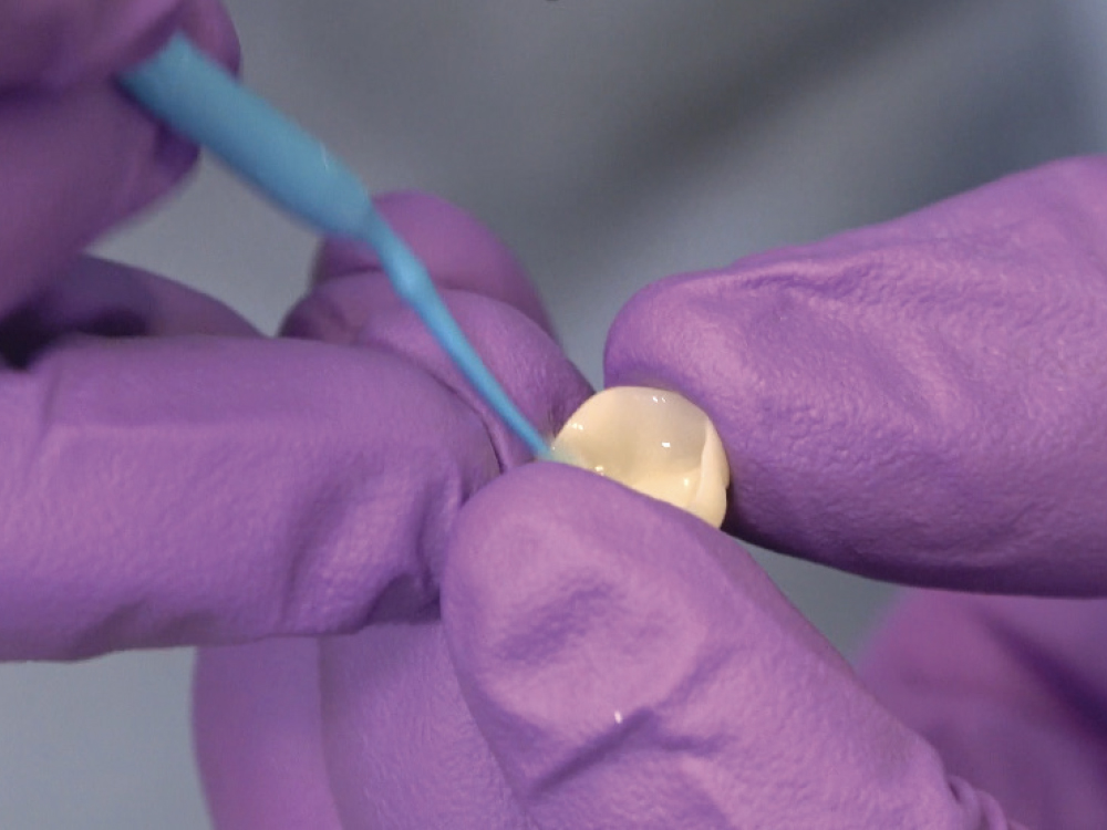
Figure 11: Once the fit was confirmed, I seated the crowns following the standard BruxZir bonding protocol. First, I lightly air abraded the inside of the crowns with 50 μm aluminum oxide, which decontaminated and roughened the surface for greater bonding potential. If the lab fabricates your BruxZir crowns, the crowns will arrive abraded. Next, Monobond® Plus (Ivoclar Vivadent; Amherst, N.Y.) was applied to the intaglio surfaces as a zirconia primer.
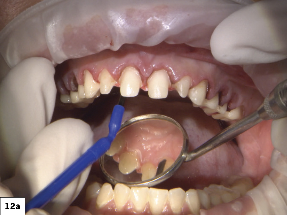
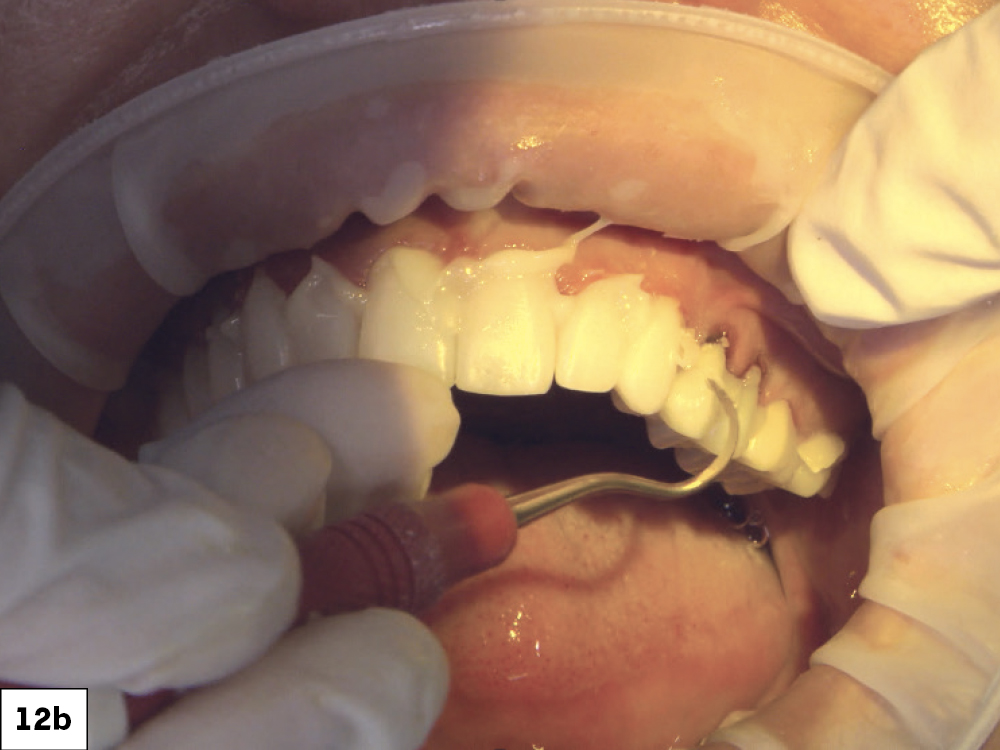
Figures 12a, 12b: On the prepared teeth, I applied GLUMA® Desensitizer PowerGel (Kulzer; Hanau, Germany) followed by ScotchBond Universal bonding agent. I used 3M RelyX™ Ultimate Adhesive Resin Cement to bond the crowns.
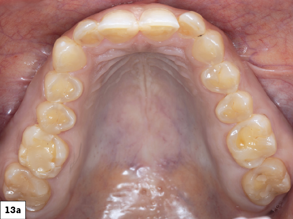
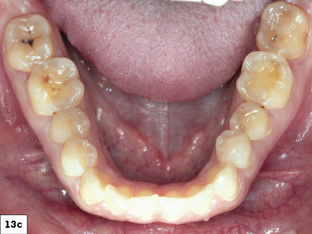
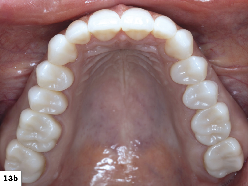
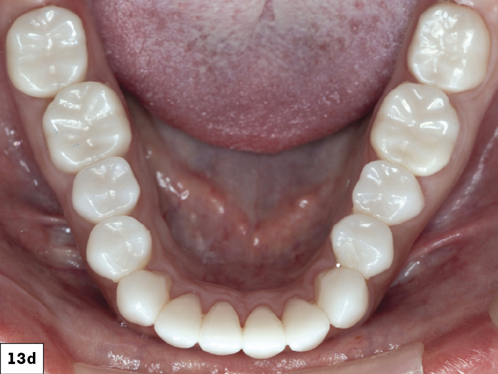
Figures 13a–13d: Once finished with the maxillary restorations, the same process was carried out for the mandibular. The crowns fit perfectly and helped restore the patient’s oral health and confidence. She was also given a Comfort H/S™ Bite Splint to protect the restorations.
The crowns fit perfectly and helped restore the patient’s oral health and confidence.
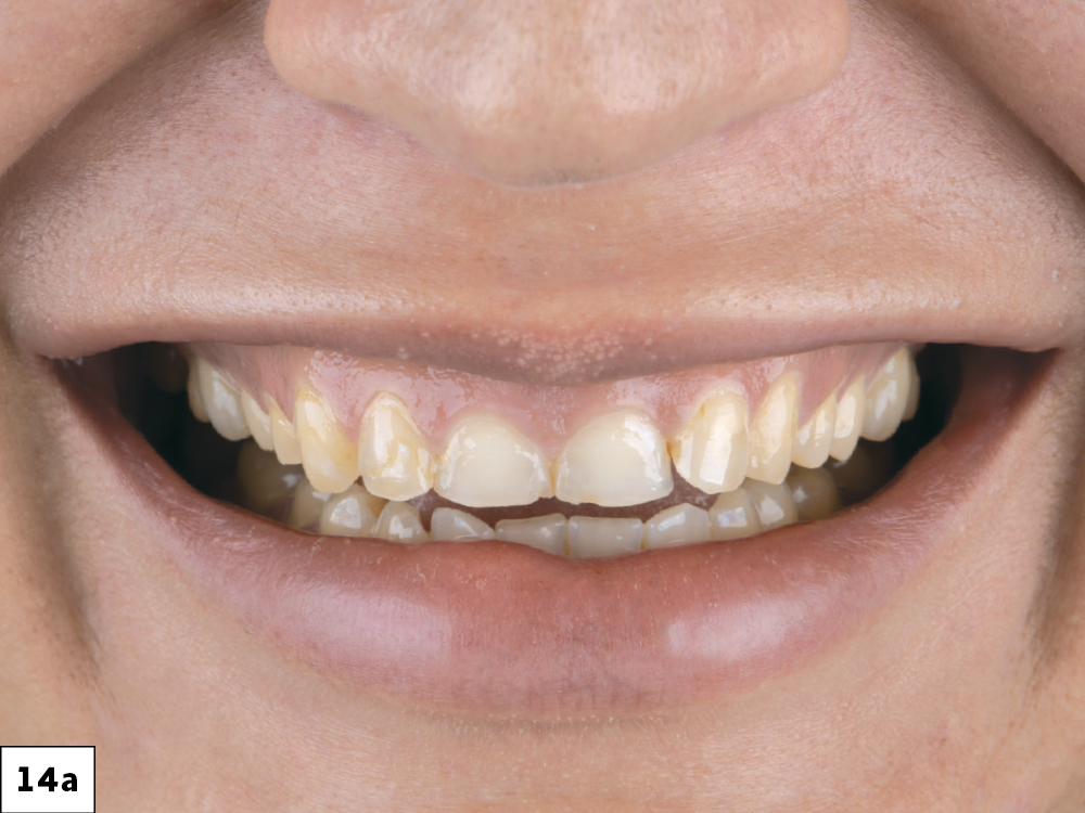
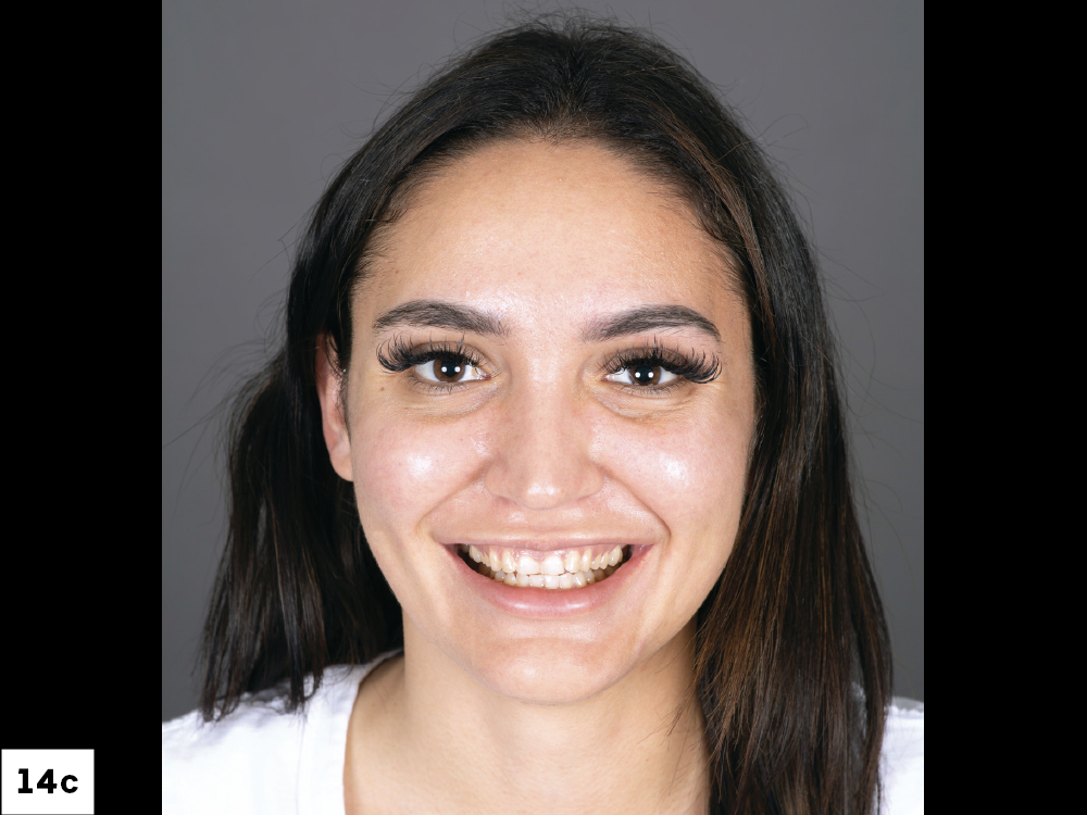
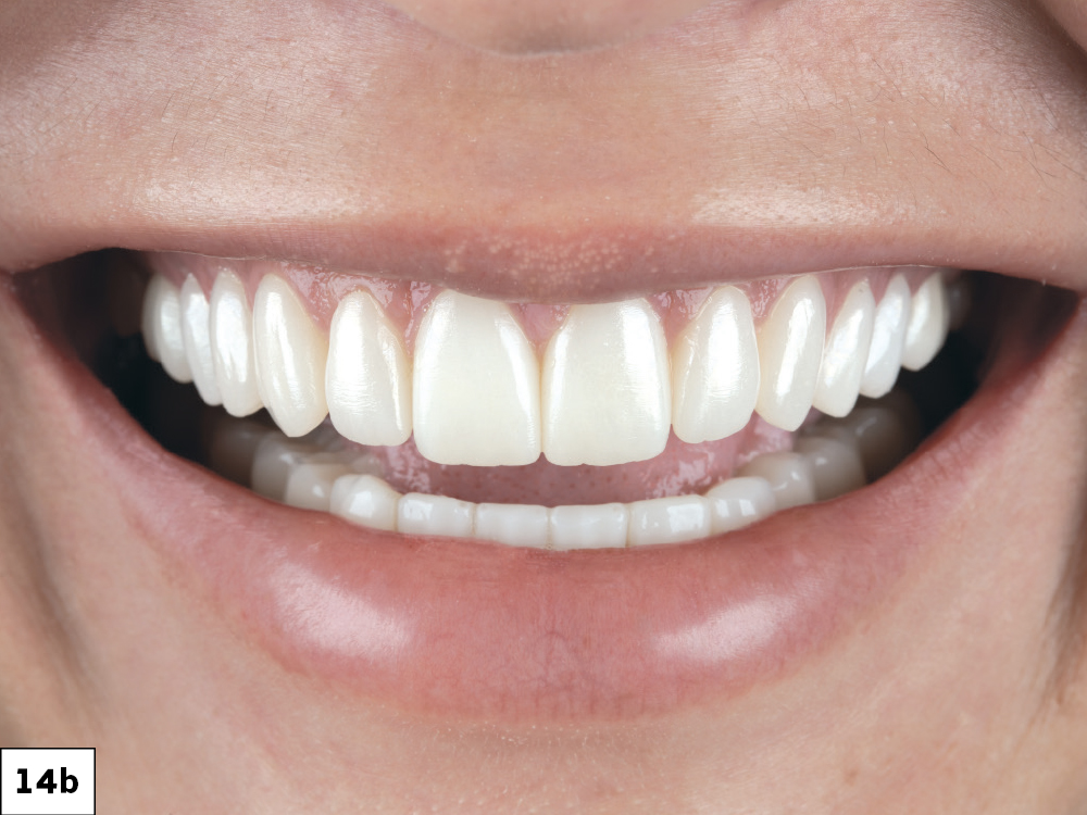
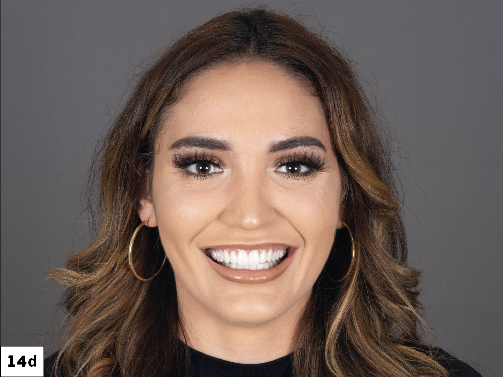
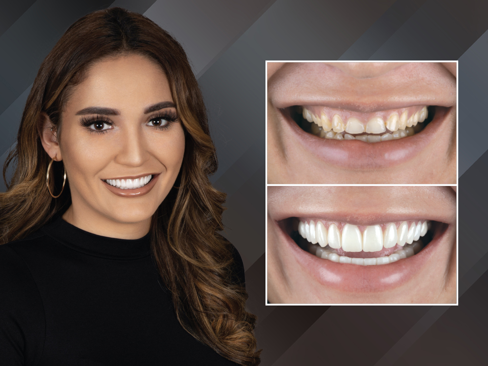
Figures 14a–14d: The patient was thrilled to see her new smile; the esthetic, natural appearance provides her with newfound self-confidence.
CONCLUSION
Chairside systems are powerful tools that provide clinicians with an abundance of possibilities even in demanding esthetic cases. By communicating closely with your lab and taking advantage of resources such as wax-ups, prep models and provisionals, clinicians can ensure highly accurate, esthetic chairside restorations.